Vehicle AC Ground Fault Detection System

Inactive Publication Date: 2009-04-09
LEAR CORP
12 Cites 18 Cited by

AI-Extracted Technical Summary

Problems solved by technology

If a passenger of the vehicle comes in contact with only one phase of the high voltage power source, then isolation between the primary and secondary of the power system ...

Benefits of technology

[0010]The present invention has the advantage of detecting a ground fault condition that would occur if a passenger contacts a single phase of a high voltage outlet and providing a signal to the power ...

Abstract

A vehicle ground fault detection system for detecting a ground fault includes a fault detection circuit having a resistance element. The resistance element has one side connected to a supply voltage. An electrical switching circuit is connected to the resistance element for selectably coupling the other side of the resistance element to a secondary ground. The fault detection circuit further includes a fault detection sense line connected to a junction between the other side of the resistance element and the electrical switching circuit. A controller selectably couples the resistance element to the secondary ground. The controller is coupled to the fault detection sense line to receive a voltage signal for detecting the ground fault prior to a start-up of the AC step-up power transformation. The controller determines a ground fault based on a comparison responsive to the voltage signal and a predetermined comparative value.

Application Domain

Technology Topic

Image

  • Vehicle AC Ground Fault Detection System
  • Vehicle AC Ground Fault Detection System
  • Vehicle AC Ground Fault Detection System

Examples

  • Experimental program(1)

Example

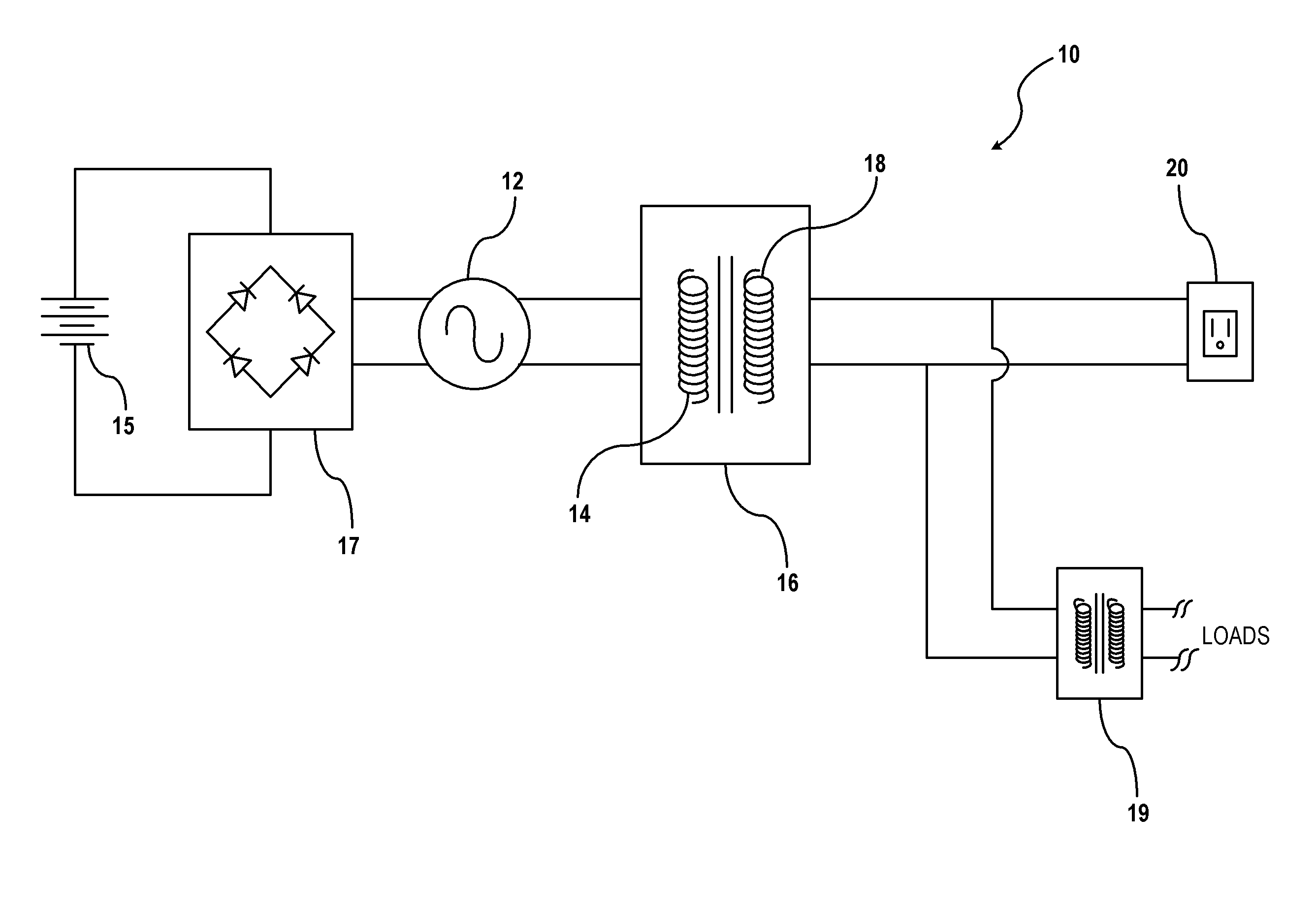
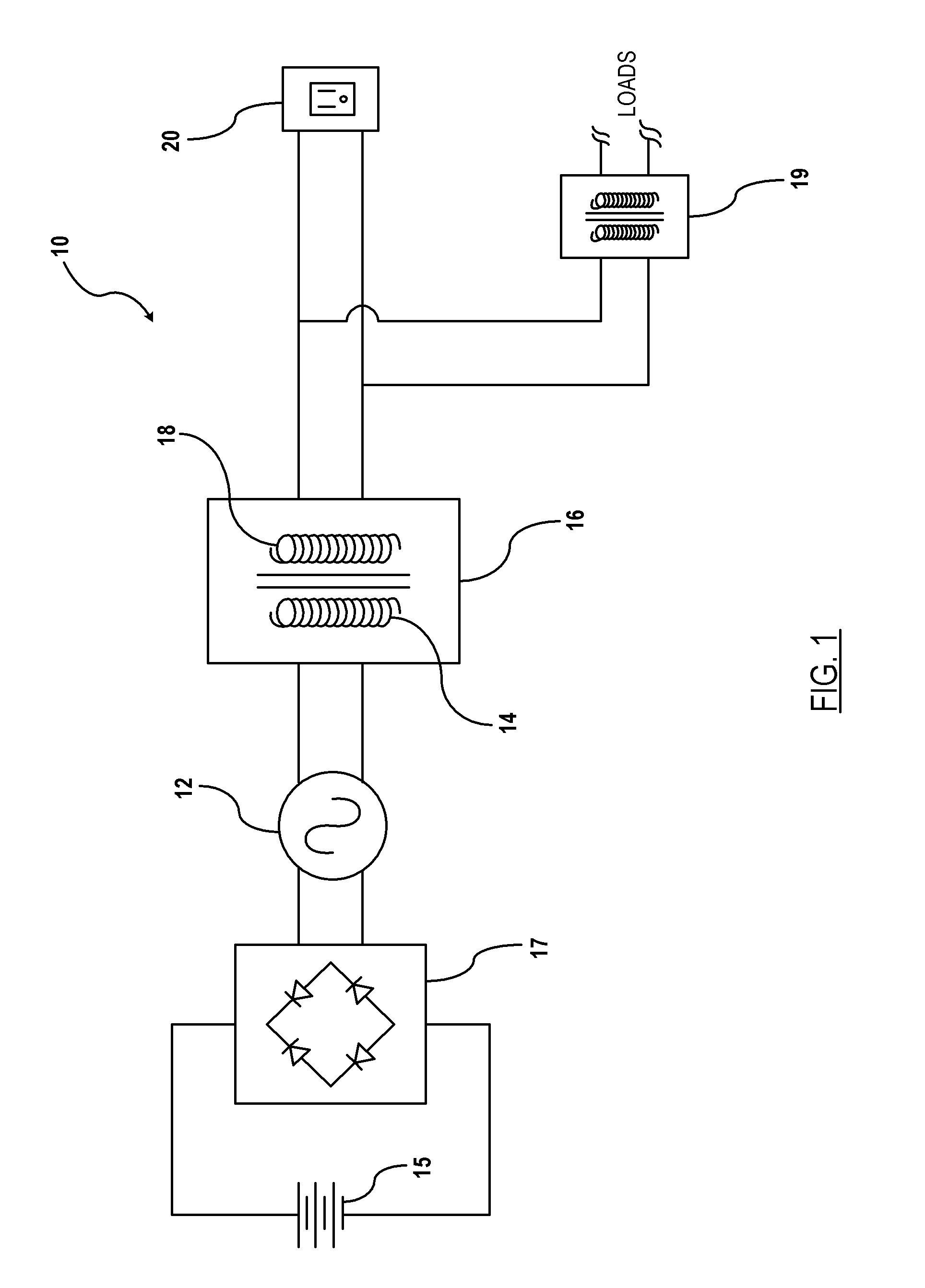
[0018]Referring now to the drawings, there is illustrated in FIG. 1 a power supply circuit, shown generally at 10, for increasing the supply voltage to a load device. The power supply circuit 10 includes supply voltage 12 that is provided to a primary coil 14 of a transformer 16. The supply voltage is a low AC voltage (e.g., 12 VAC) converted from DC power source 15. The DC power is converted to the supply voltage via inverter shown generally at 17. The power provided to the primary coil 14 is stepped up to a high AC voltage such as 220 VAC or 400 VAC) at the secondary coil 18. An electrical outlet 20 is coupled to the secondary coil 18 for electrical coupling to an AC-based personal convenience device. The power supply circuit 10 may include one or more additional transformers 19 for stepping down or up the voltage for supplying AC power to various loads 19 throughout the vehicle. The present invention provides a means for detecting an object in contact with a respective phase generated by the high voltage side of the transformer 16.
[0019]FIG. 2 illustrates an electrical schematic of the fault detection system 22. The fault detection system 22 includes an electrical switching circuit 24 connected to a secondary ground 26. The secondary ground 26 is a same ground as that of the secondary coil 18 of the AC transformer 16 (FIG. 1). The electrical switch circuit 24 is electrically connected to an input supply voltage line 28. The input supply voltage line 28 includes a resistance element 30, such as a resistor, having a predetermined resistance value. The input supply voltage line 28 is connected to a supply voltage 32 from a DC supply source. The resistance element 30 is coupled on the input supply voltage line 28 between the supply voltage source and the electrical switching circuit 24.
[0020]A control input command signal 34 is transmitted on a control signal line 36 which is connected to the electrical switching circuit 24. The control input command signal 34 transmitted to the electrical switching circuit 24 commands the electrical switching circuit 24 to internally couple the input supply voltage line 28 to the secondary ground 26. This provides a known voltage and current input to the secondary ground 26.
[0021]A fault detection sense line 38 is coupled to the input supply voltage line 28 between the resistance element 30 and the electrical switching circuit 24. The fault detection sense line 38 is coupled to a microprocessor 40 or similar device for monitoring the voltage on the fault detection sense line 38. Preferably, the microprocessor 40 is not integrated as part of electrical switching circuit 24 but is part of another electrical component/subsystem since the use of a dedicated microprocessor solely for the fault detection system would be unwarranted and not cost effective. However, in alternative embodiments microprocessor may be integrated within the electrical switching circuit or the microprocessor itself may be used as the switching circuit.
[0022]The fault detection operation occurs prior to the start up the AC step-up power transformation. That is, prior to the ignition being turned on and the AC transformer being energized for stepping up the AC voltage, a fault detection routine is initiated. The supply voltage (e.g., 5 Vdc) is provided on the input supply voltage line 28. Prior to electrical switching circuit 24 receiving a control input command signal 34, the input supply voltage line 28 is open or at least not coupled to the secondary ground 26. When a control input command signal 34 is provided to the electrical switching circuit 24, the electrical switching element 24 internally connects the input supply voltage line 28 to the secondary ground 26. The microprocessor 40 monitors the fault detection sense line 38. The architecture of the fault detection sense line 38, resistance element 30, and the secondary ground 26 form a voltage bridge divider. The voltage measured by the microprocessor 40 represents the low-side resistor voltage. Either the measured voltage or a comparative value that is a function of the measured voltage can be compared with a predetermined comparative value for determining the ground fault. A comparative value that is a function of the measured voltage such an isolation resistance can be determined the based on the voltage bridge divider using the following formula:
Risolation=(R1*Vmeasured)/(Vcc−Vmeasured)
[0023]where R1 is the resistance value of the resistance element 30, Vmeasured is the voltage measured by the on the fault detection sense line 38, and Vcc is the supply voltage 32. Based on the determined isolation resistance a ground fault may be detected. For example, if the resistance element 30 has a resistance value of 100 kΩ, then a calculated isolation resistance value (Risolation) of 80 kΩ or less is indicative that an object creating a short between the secondary ground and the battery ground. As a result, the fault detection can be detected. Therefore, for a resistance element having a predetermined resistance value, a predetermined isolation resistance (or predetermined voltage) is compared with the calculated isolation resistance (or measure voltage) on the fault detection sense line 38 for indicating whether a fault is present in the AC electrical system.
[0024]FIG. 3 illustrates a schematic of a fault detection circuit according to a second preferred embodiment. An electrical switching circuit 50 is shown having a relay 52 and a power switch 54. The relay 52 includes a relay coil 56. An input of the relay coil 56 is coupled to a battery voltage 58. An output of the relay coil 56 is coupled to the power switch 54 which will be discussed in detail below. When the relay coil 56 is coupled to ground, the relay coil 56 is energized and the relay 52 connects the input supply voltage line 28 to the secondary ground 26 as described.
[0025]The output of the relay coil 56 is coupled to the collector 60 of the power switch 54. The fault detection sense line 38 is coupled to the base 62 of the power switch 54. The emitter 64 is coupled to a battery ground 66. When a control command input signal 34 is generated on the fault detection sense line 38 to the base 62, an electrical connection is completed between the collector 60 and the emitter 64 and thereafter to the battery ground 66. As a result, the output of the relay coil 56 is connected to battery ground 66 thereby allowing current flow to energize the relay coil 56. Energizing the relay coil 56 connects the input supply voltage line 28 to the secondary ground 26 via the relay 52. The microprocessor 40 thereafter monitor the fault detection sense line 38 for detecting a fault.
[0026]Alternatively, the power switch 54 may include a power relay, Mosfet, or other similar device. Moreover, the electrical switching circuit may include other electrical configurations including but not limited to an ASIC. It must be understood that this invention may be practiced otherwise than as specifically explained and illustrated without departing from its spirit or scope, and that other electrical components may be used to monitor and couple the input supply voltage line to the secondary ground so that a fault may be detected within the AC electrical power transformation system.

PUM

no PUM

Description & Claims & Application Information

We can also present the details of the Description, Claims and Application information to help users get a comprehensive understanding of the technical details of the patent, such as background art, summary of invention, brief description of drawings, description of embodiments, and other original content. On the other hand, users can also determine the specific scope of protection of the technology through the list of claims; as well as understand the changes in the life cycle of the technology with the presentation of the patent timeline. Login to view more.

Similar technology patents

System for controlling mechanical automatic gear system

InactiveCN103608601APrevent shockCurbing cost increasesClutchesClutchGear system
Owner:MITSUBISHI FUSO TRUCK AND BUS CORPORATION

Immune cell activation inhibitor and use thereof

InactiveUS20150202170A1Inhibit activationAntibacterial agentsUrea derivatives preparationInflammatory skin diseaseDrug
Owner:NAT UNIV CORP EHIME UNIV

Pharmaceutical composition for preventing or treating inflammatory diseases, allergic diseases or asthma, containing diospyros blancoi a. dc. extract as active ingredient

ActiveUS20130164395A1Inhibit activationSuppress secretionBiocideAntipyreticInflammatory skin diseaseBronchoalveolar lavage
Owner:KOREA RES INST OF BIOSCI & BIOTECH

Classification and recommendation of technical efficacy words

  • Inhibit activation
  • Prevent shock

Thiazole and thiadiazole compounds for inflammation and immune-related uses

InactiveUS20070254925A1Suppress immune systemInhibit activationBiocideSenses disorderHypersensitivity DiseasesImmune disorder
Owner:SYNTA PHARMA

Use of specific T2R taste receptors to identify compounds that block bitter taste

ActiveUS20030170608A1Block bitter tasteInhibit activationCompound screeningApoptosis detectionDrug6-nitrosaccharin
Owner:SENOMYX INC

Uses of inhibitors for the activation of CXCR4 receptor by SDF-1 in treating rheumatoid arthritis

InactiveUS20050202005A1Inhibit activationOrganic active ingredientsAntibody ingredientsInflammatory arthropathyMedicine
Owner:THE TRUSTEES OF COLUMBIA UNIV IN THE CITY OF NEW YORK

System for controlling mechanical automatic gear system

InactiveCN103608601APrevent shockCurbing cost increasesClutchesClutchGear system
Owner:MITSUBISHI FUSO TRUCK AND BUS CORPORATION
Why Eureka
Try Eureka