LED-based dental exam lamp with variable chromaticity

a technology of variable chromaticity and led-based dental exam lamps, which is applied in the field of apparel, can solve the problems of inefficient conversion process, large heat generation of incandescent lights, and inefficient conversion of electricity to visible light, and achieves reduced intensity illumination, high intensity, and easy to understand and appreciate

Active Publication Date: 2009-04-09
KAVO DENTAL TECH
View PDF100 Cites 46 Cited by
  • Summary
  • Abstract
  • Description
  • Claims
  • Application Information

AI Technical Summary

Problems solved by technology

However, such incandescent lights suffer from an inefficient conversion of electricity to visible light.
The inefficient conversion process causes production of a considerable amount of heat, and emission of a significant amount of radiation in, or near, the infrared spectrum.
The heat generated by incandescent lighting may sometimes place an undesirable burden on environmental control systems, such as cooling systems used in dwellings.
Both the inefficient conversion process, and removing the undesired heat load from the area near the light, lead to a correspondingly larger than necessary electric utility bill.
Furthermore, in use on an operatory to illuminate an operating site on a patient, the infrared emissions may undesirably dry illuminated tissue, or may produce a feeling of discomfort in the patient.
However, fluorescent bulbs tend to be bulky, and generally produce light of a less desirable color and intensity for many applications.
Furthermore, certain electrical components required in the electric circuit powering the fluorescent bulbs, such as the ballast, tend to produce an undesirable amount of noise.
These incandescent dental exam lights possess a number of disadvantages, such as: emission of infra-red (IR) radiation that must be removed with filters or so-called ‘cold-mirrors’ to prevent excessive warming of the patient and user; relatively short bulb life-time; inability of the user to adjust light color temperature and chromaticity of light; color temperature becoming lower and the light becoming “warmer” (i.e., shifting from white to orange / red), when light intensity is reduced (dimmed); and production of significant ultraviolet (UV) and blue light which causes undesired and uncontrolled curing of dental composites and adhesives.

Method used


Image

  • LED-based dental exam lamp with variable chromaticity
  • LED-based dental exam lamp with variable chromaticity
  • LED-based dental exam lamp with variable chromaticity

Examples


Embodiment Construction

[0016]Although the foregoing description contains many specifics, these should not be construed as limiting the scope of the present invention, but merely as providing illustrations of some representative embodiments. Similarly, other embodiments of the invention may be devised that do not depart from the spirit or scope of the present invention. Features from different embodiments may be employed in combination.

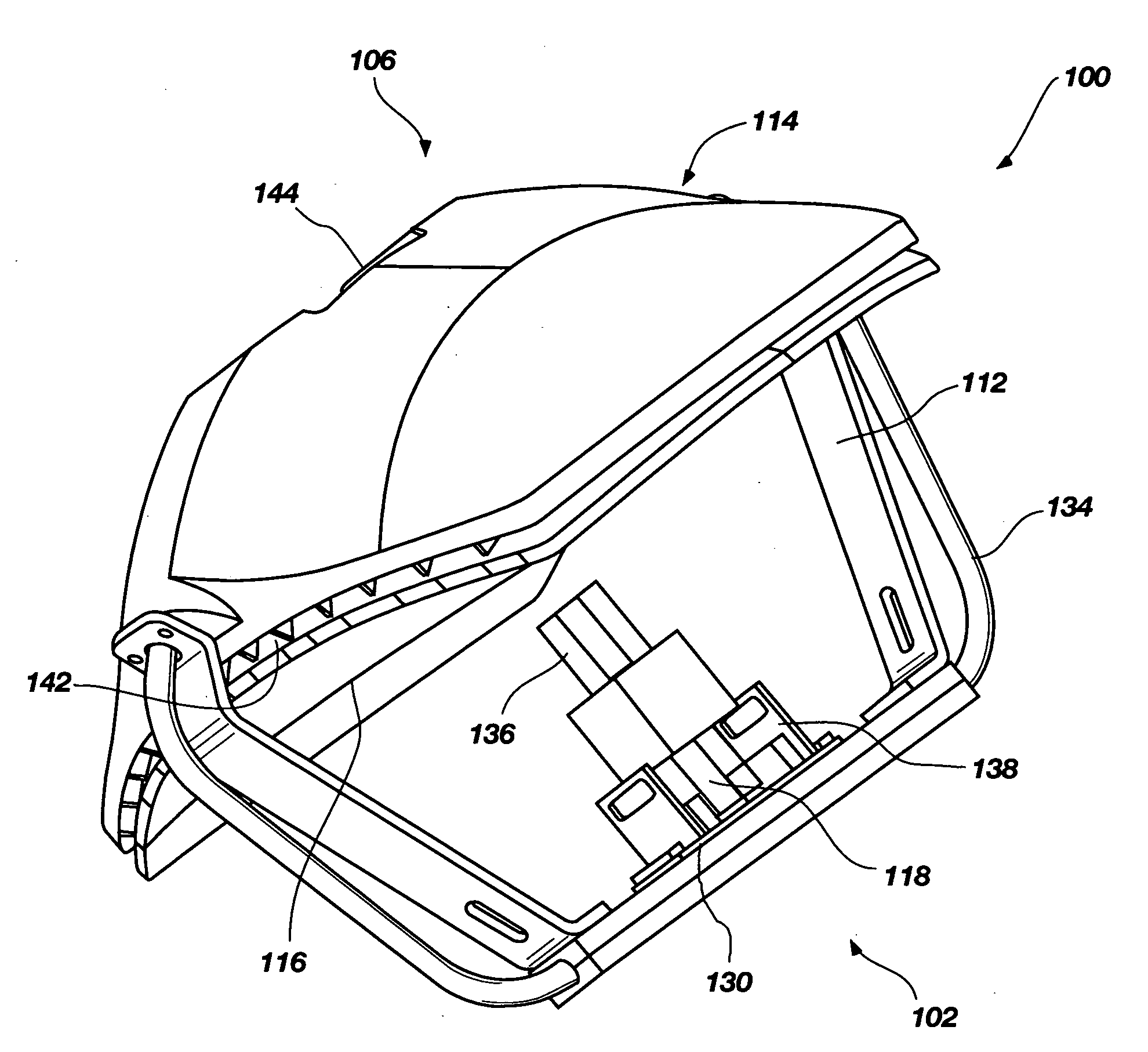
[0017]FIG. 1 illustrates a perspective view of a current embodiment of the invention, generally indicated at 100, of a light source structure constructed according to principles of the invention. Light source structure 100 may generally be characterized as a lamp. Lamp 100 is powered by electricity, and functions to provide illumination to a work area disposed a distance from the lamp front, generally indicated at 102. Desirably, the work area illuminated by lamp 100 is shadow-free, and appears relatively uniform in illumination color and intensity. For most applications, th...


PUM


Abstract

An electrically powered light source including a light emitting diode (LED) having variable chromaticity, which is adapted for use in a dental operatory. A dental operatory lamp includes a thermally conductive housing having a front directed toward the operating area and a rear away from the operating area; a generally elliptical reflector located on the rear of the thermally conductive housing; at least one heat pipe; a plurality of color LEDs projecting light toward the elliptical reflector, the plurality of LEDs being in thermal contact with the at least one heat pipe; and an optical light guide for combining light from said LEDs. Another embodiment of the lamp includes at least two user selectable light spectra, one of said spectra providing white light with color temperature in the range 4000° K-6000° K and one spectra having reduced output in the wavelength range 400-500 nm.

Description

RELATED U.S. APPLICATION DATA[0001]This application is a continuation-in-part of application Ser. No.11 / 867,876, filed Oct. 5, 2007, published as Pub. No. US 2008 / 0025013 A1 on Jan. 31, 2008. The disclosure of the previously referenced U.S. patent application is hereby incorporated herein by reference in its entirety.TECHNICAL FIELD[0002]This invention relates to apparatus that produce visible light. It is particularly directed to an electrically powered light source including a light emitting diode (LED) having variable chromaticity, which is adapted for use in a dental operatory.BACKGROUND[0003]It has been known for an extended period of time that electricity may be harnessed to create visible light. Incandescent light emitting elements powered by electricity have been used for substantially the same period of time. However, such incandescent lights suffer from an inefficient conversion of electricity to visible light. The inefficient conversion process causes production of a cons...

Claims


Application Information

Patent Timeline
Patent Type & Authority Applications(United States)
IPC IPC(8): F21L27/00
CPCF21Y2101/02F21V7/0008F21V7/08F21V13/04F21V29/89F21W2131/202F21V29/006F21V29/74F21V29/83F21V29/004F21Y2115/10F21V29/51F21V29/507
Inventor LI, WEISWAYNE, JAMIEUNSWORTH, AUSTIN E.DAGHER, NABILLOCKAMY, H. THOMAS
Owner KAVO DENTAL TECH
Why Eureka
Try Eureka