Packet communication device, packet communication system, packet communication system, packet communication module, data processor, and data transfer system

a packet communication and video data technology, applied in data switching networks, data switching by path configuration, digital transmission, etc., can solve the problems of packet loss, transfer buffer overflow, packet loss, etc., and achieve the effect of buffer area storage capacity

Inactive Publication Date: 2009-04-09
RENESAS ELECTRONICS CORP
View PDF6 Cites 10 Cited by
  • Summary
  • Abstract
  • Description
  • Claims
  • Application Information

AI Technical Summary

Benefits of technology

[0054]From the viewpoint of how to cope with the concentration of communication data in one network controller, dynamic variable control of the storage capacity of buffer areas is effective. To be more specific, with reference to a FIFO buffer size specified in the buffer size information, as a result of comparison between the storage capacity of a buffer area used in a direction from one data communication channel to the other communicati

Problems solved by technology

In the prior art, instead of applying the packet communication device to the IP phone, a case where the packet communication device is applied to an IP videophone which transmits video data is not sufficiently considered.
If the packet communication device is applied to the IP videophone, there is a possibility that the transfer buffer will overflow.
As a result, the transfer of a packet from the PC side is delayed, causing a transfer buffer which temporarily holds packets from the PC side to over

Method used


Image

  • Packet communication device, packet communication system, packet communication system, packet communication module, data processor, and data transfer system
  • Packet communication device, packet communication system, packet communication system, packet communication module, data processor, and data transfer system
  • Packet communication device, packet communication system, packet communication system, packet communication module, data processor, and data transfer system

Examples


Embodiment Construction

[0086]Embodiments of the present invention will be described with reference to drawings below.

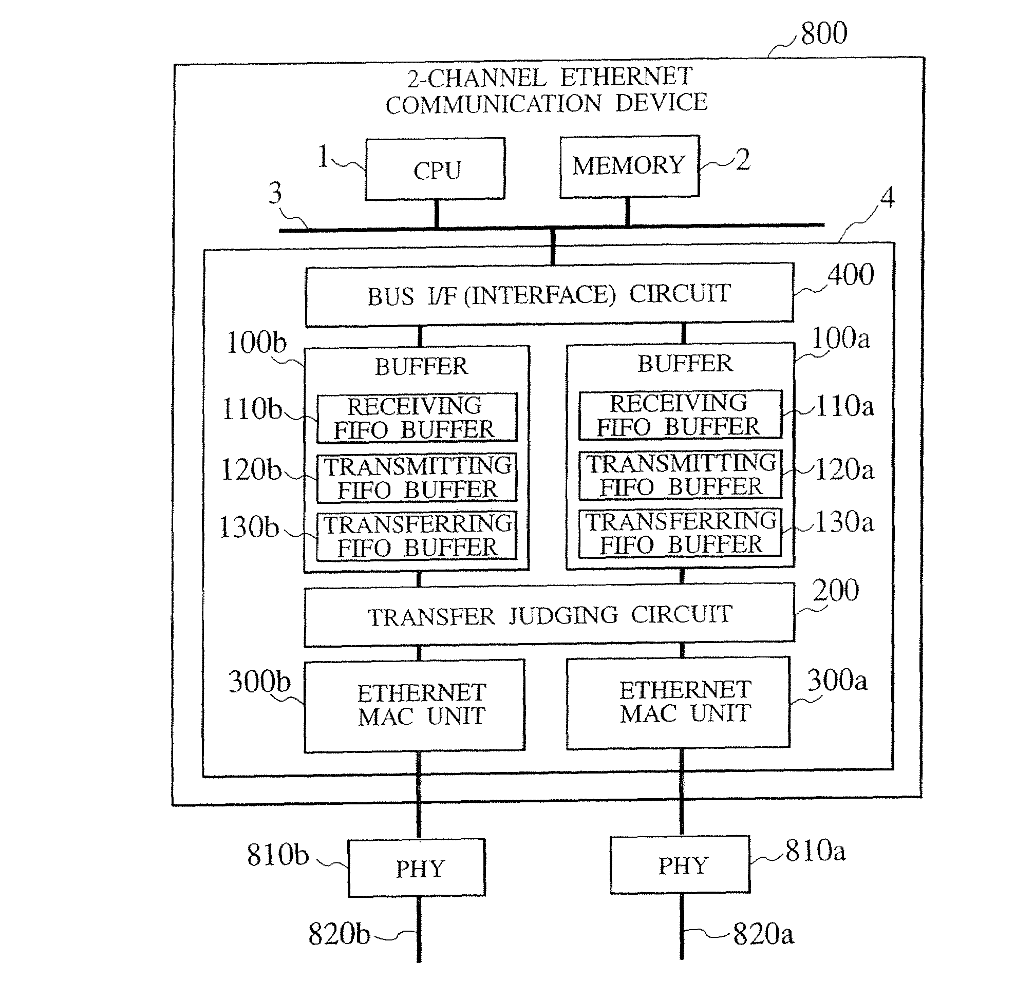
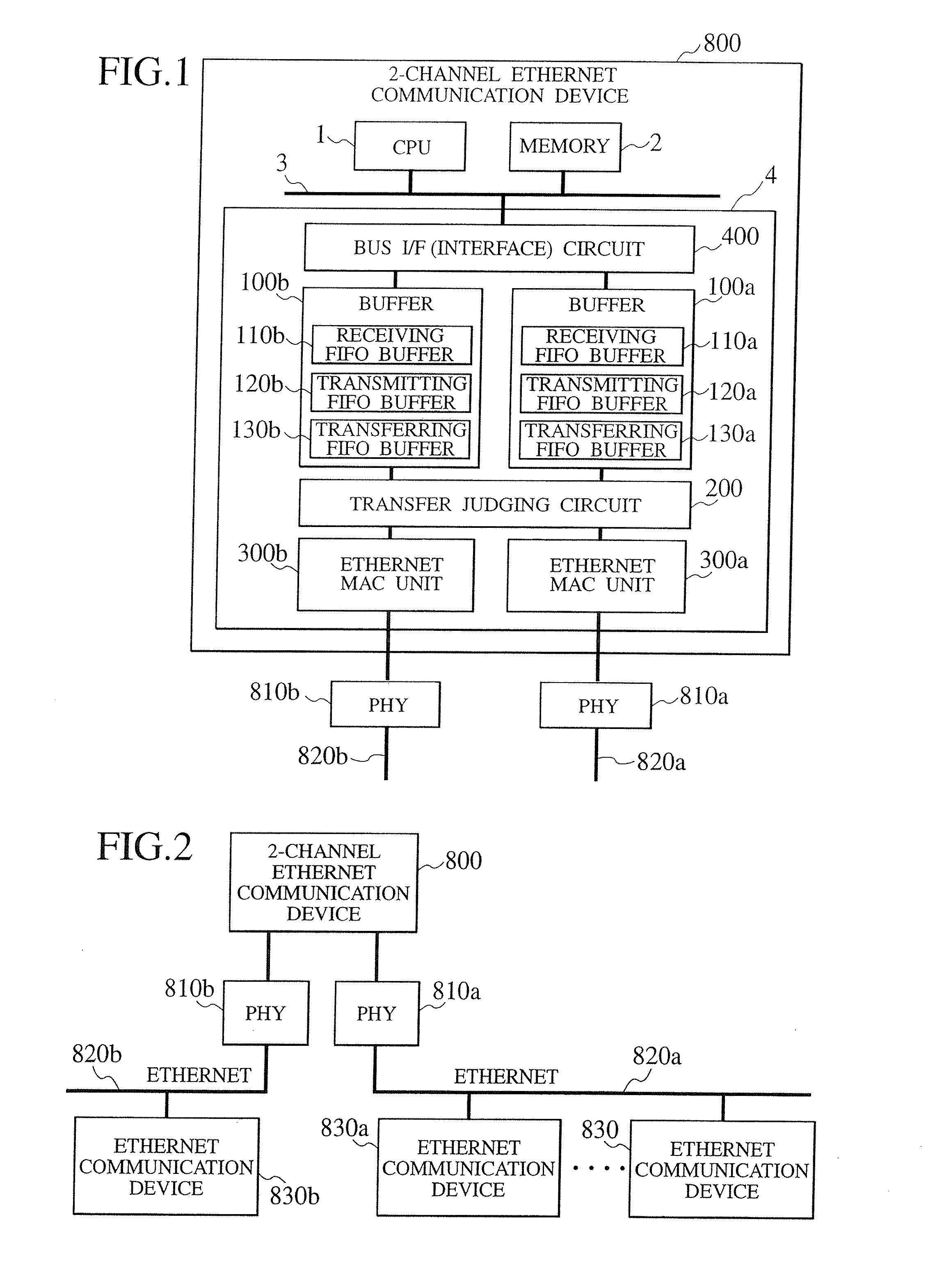
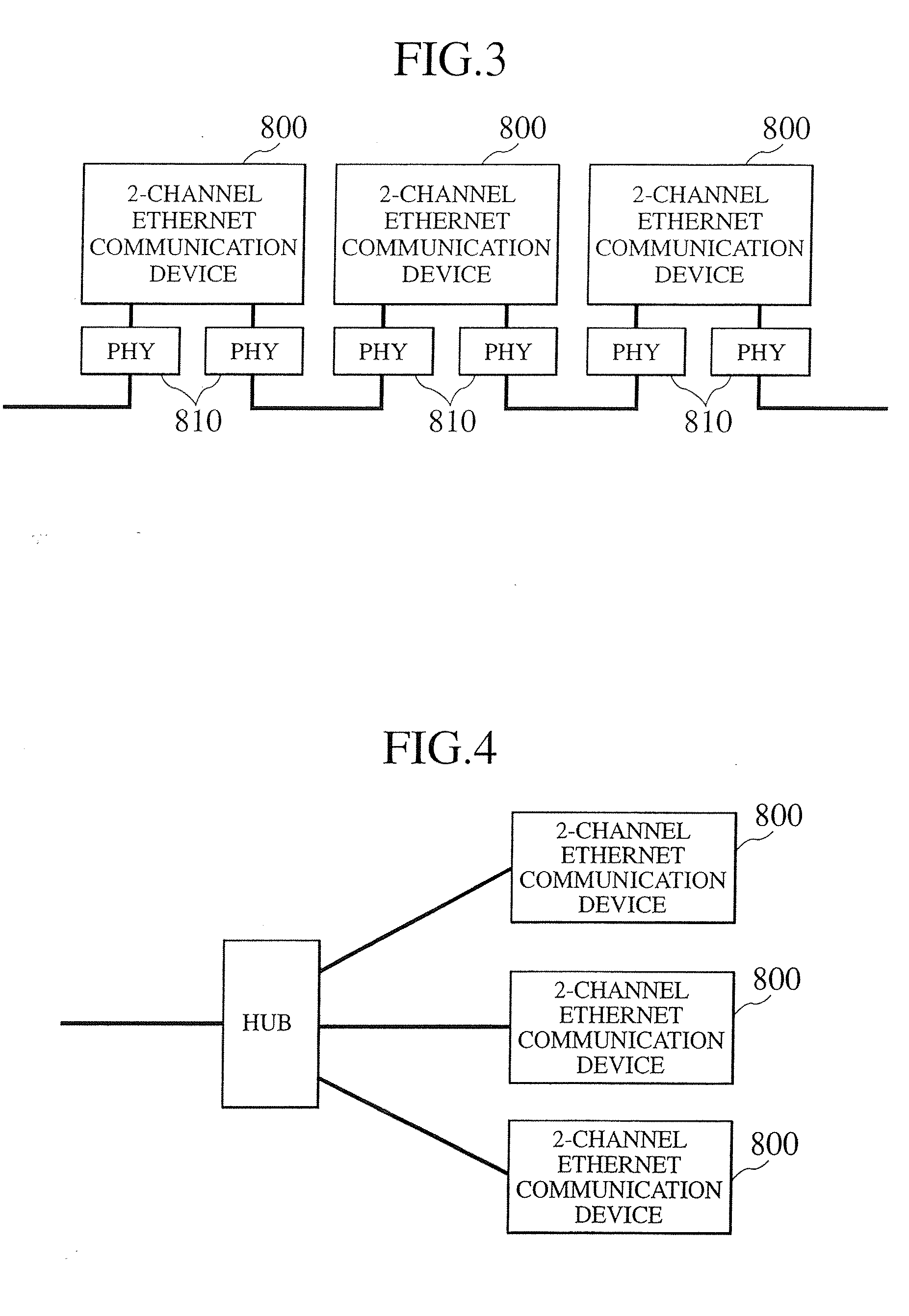
[0087]FIG. 1 is a block diagram illustrating a configuration of a packet communication device according to one embodiment of the present invention. FIG. 2 is a block diagram illustrating a configuration of a packet communication system. This configuration is used when the packet communication device according to the present invention is applied to a 2-channel Ethernet network. In FIG. 2, a 2-channel Ethernet communication device 800 as a packet communication device has communication paths (communication means) equivalent to two channels. The communication paths, each of which corresponds to each channel, are connected to Ethernet 820a, 820b through PHY (Physical layer transceiver) 810a, 810b, respectively. Ethernet communication devices 830a, 830b, each of which comprises a PC (personal computer), are connected to the Ethernet 820a, 820b, respectively. Each of the Ethernet 820a, 820b is con...


PUM


Abstract

A transmit packet generated by a CPU 1 is held in a buffer 100a (100b). From among packets received from Ethernet 820a (820b), a packet, a destination of which is a communication device 800, is held in the buffer 100a (100b). A packet which should be transmitted is transmitted from a transfer judging circuit 200 to Ethernet 820a or 820b through a MAC unit 300a or 300b. If a transfer judging circuit 200 judges a packet from the Ethernet 820a to be a packet, a destination of which is another communication device, with reference to a destination MAC address, this packet is transferred to the Ethernet 820b through MAC 300b. If a usage rate of a transferring FIFO buffer 130a (130b) exceeds a threshold value in the process of transmitting a packet held in a transmitting FIFO buffer 120a (130b) on a priority basis, the priority order of a transfer packet is made higher than that of a transmit packet so that the transfer packet is transferred to the Ethernet 820a or 820b in preference to the transmit packet. This prevents a transfer buffer means from overflowing.

Description

BACKGROUND OF THE INVENTION[0001]The present invention relates to a packet communication device, a packet communication system, a packet communication modules a data processor, and a data transfer system, each of which comprises at least two network controllers or two data communication channels.[0002]There is known, as a communication device using a packet, a device used for an IP phone, etc., which exchanges audio data using IP (Internet Protocol) on the basis of Ethernet. This kind of packet communication device comprises a CPU, two Ethernet controllers, a transfer control circuit, and a memory. As a method for reducing the number of Ethernet cables which are connected from the HUB, the following method is adopted: one Ethernet controller is connected to a HUB via Ethernet; the other Ethernet controller is connected to a PC (personal computer) via Ethernet; and the HUB is connected to the PC through the communication device. This packet communication device is so devised that if ...

Claims


Application Information

Patent Timeline
IPC IPC(8): H04L12/28H04L12/44H04L12/56
CPCH04L12/44H04L47/10H04L47/2458H04L47/30H04L49/351H04L47/6255H04L49/205H04L49/3018H04L47/522
Inventor ARITA, HIROSHINAKATSUKA, YASUHIROWATANABE, TASUWOOUCHI, KEITANAKA, YOSHIHIROKANAI, TOSHINOBUTANAKA, MASANOBUFURUHASHI, KENJIAOKI, TOMOAKI
Owner RENESAS ELECTRONICS CORP
Why Eureka
Try Eureka