Low bending loss multimode fiber transmission system

a transmission system and low bending loss technology, applied in the field can solve the problems of increased loss of bend resistant fibers, limited size of such devices, and application of such systems in various single-mode applications, and achieve the effect of low bend losses

Active Publication Date: 2009-04-09
LUMENTUM D O O OPTICNA VLAKNA
View PDF16 Cites 84 Cited by
  • Summary
  • Abstract
  • Description
  • Claims
  • Application Information

AI Technical Summary

Benefits of technology

[0008]It is a preferred object of the present invention to provide a multimode fiber transmission system which has low bend losses and is therefore bend resistant, i.e. bend-loss resistant or bend-loss tolerant.

Problems solved by technology

Sizes of such devices are limited by the bend loss tolerance of optical fibers used.
Many of the presented solutions reduce the mode field diameter of the fundamental mode, when compared to standard single mode fiber such as Corning SMF-28, resulting in an increased loss when bend resistant fibers are spliced to standard telecommunication fiber.
While the transmission channel is single mode, the presence of higher order modes cannot be completely excluded, which prohibits application of such systems in various single-mode applications.
However, there are only few and limited solutions that can improve bend tolerance of multimode transmission systems.
There are several serious limitations that restrict design opportunities for bend resistant multimode fibers.
Since multimode fibers support a large number of modes and each mode bears individual bend loss characteristics, it is difficult to control bend loss and other waveguide properties of all propagating modes at once.
In general, groups of modes that have high effective refractive index also exhibit high bend tolerance, while groups of modes with low effective refractive index show poor bend performance.
Furthermore, it is often desired that the multimode fiber profile minimizes differences in group velocities between propagating modes, otherwise the modal dispersion and thereby bandwidth of the transmission multimode fiber can become severely degraded.
This is especially true of high bandwidth transmission multimode fibers where even minor intervention into the optimum shape of the graded index profile inevitably leads to serious degradation of transmission fiber bandwidth.
The trench depth and width is limited by the production process in silica fibers and also by propagation of spurious modes guided by the trench that can severely degrade the fiber performance.
Location of the trench close to the fiber core also affects higher order mode group velocities that can result in significant degradation of fiber bandwidth.
The holey fibers are difficult to splice, and the high index contrast holes can compromise the fiber bandwidth and can induce additional guidance losses while providing limited improvement in bend loss performance.

Method used


Image

  • Low bending loss multimode fiber transmission system
  • Low bending loss multimode fiber transmission system
  • Low bending loss multimode fiber transmission system

Examples


Embodiment Construction

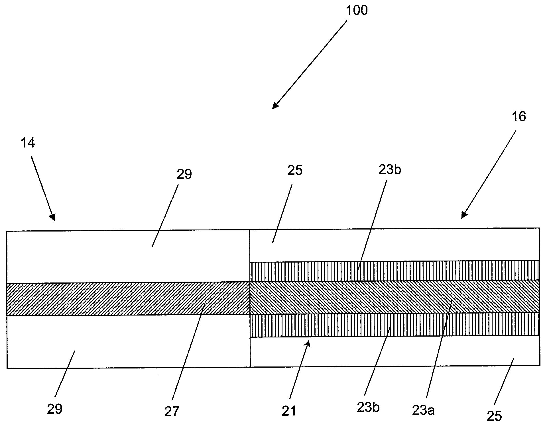
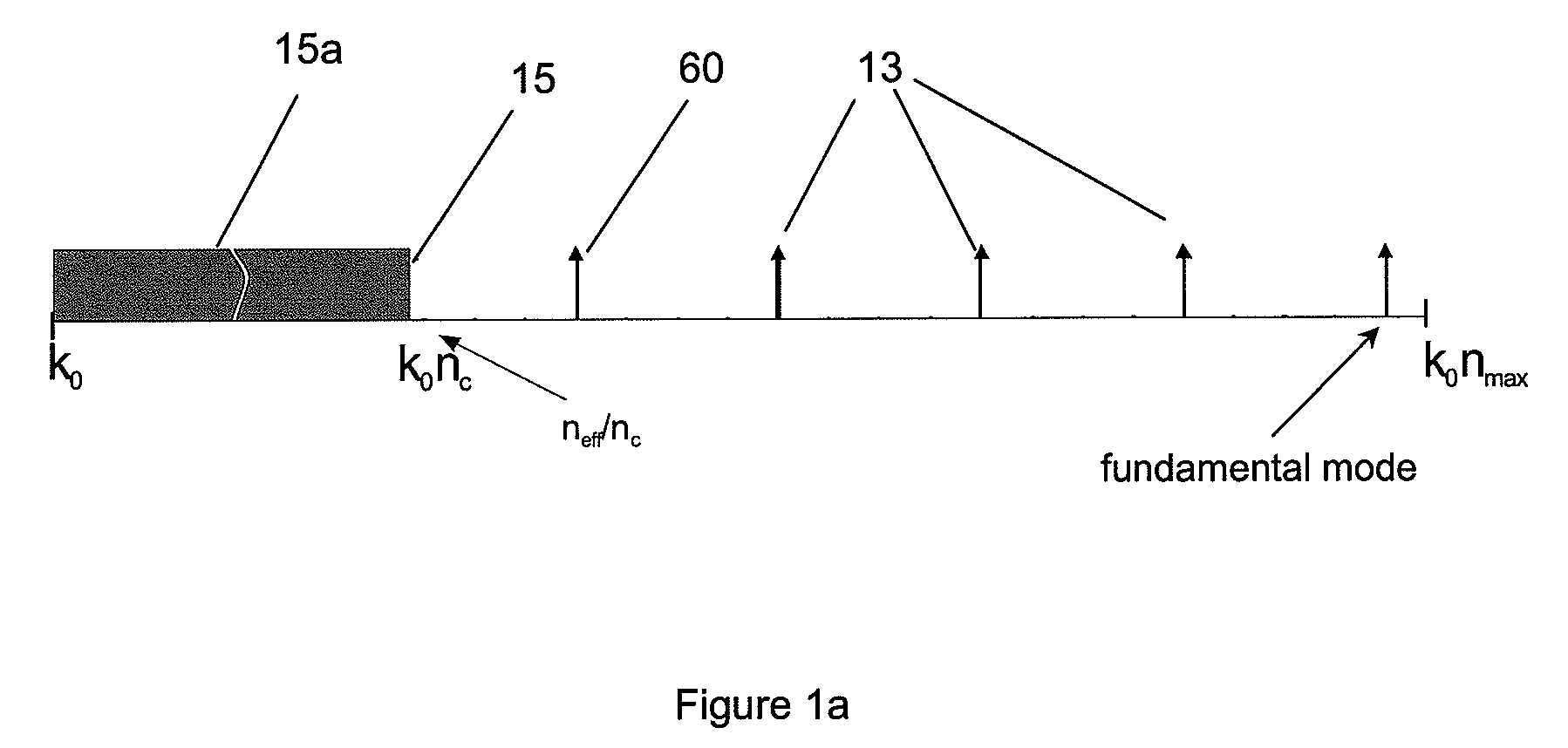
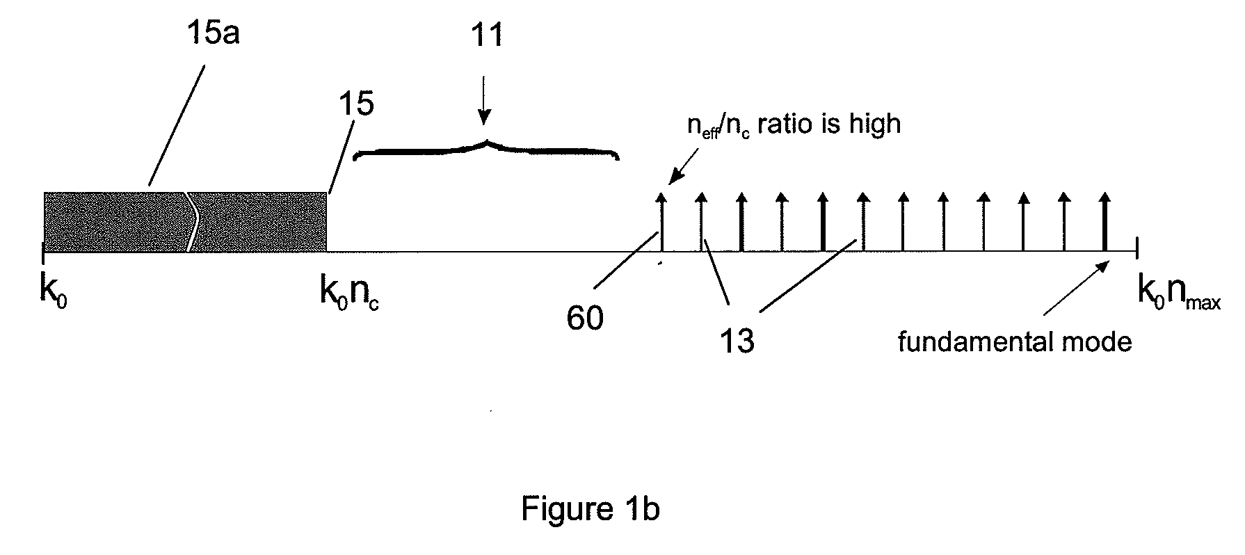
[0061]The present invention will be described more fully hereinafter with reference to the accompanying drawings, FIGS. 1 to 11.

[0062]In accordance with an embodiment of present invention, there is provided a high bend-loss tolerant multimode fiber transmission system, which may also be compatible (assure low splicing loss) with standard or other multimode fibers and provide low modal dispersion and thereby maintain bandwidth similar to standard telecom multimode fibers. It is to be understood that the expression “bend-loss tolerant” is used herein to refer to a fiber transmission system in which a bending of the transmission fiber induces no losses or low loss of the light guided by the system, within acceptable limits of the target application. The expressions “bend-loss tolerant”, “bend-resistant”, “bend-loss resistant” and “bend tolerant” are used herein interchangeably.

[0063]When an optical fiber is exposed to bending, two types of bend-related losses are generally encountered:...


PUM


Abstract

A bend-loss tolerant multimode fiber transmission system is provided. The system includes: a transmission fiber having a core and a cladding, and a mode-launching system for selectively exciting only a useful portion of the transmission modes, that portion corresponding to high effective refractive indices relative to a refractive index of the cladding the useful portion corresponding to a substantial number of modes. The mode-launching system may include a lead-in fiber, coupled to the transmission fiber, supporting a number of lead-in modes substantially corresponding to the number of transmission modes in the useful portion. The transmission fiber may have a refractive index profile, within a region of its core that is aligned with the lead-in fiber core, which has a shape that matches a refractive index profile shape in the lead-in fiber core. The transmission fiber core may have a graded refractive index profile that is parabolic or nearly parabolic or truncated.

Description

FIELD OF THE INVENTION[0001]The present invention relates generally to bend resistant fibers for optical communication and other fiber optic systems. More particularly, the present invention is directed to a multimode fiber transmission system which is highly resistant to the loss caused by bending of the transmission fiber.BACKGROUND OF THE INVENTION[0002]Attenuation of optical signal in optical fibers caused by the fiber or cable bending has been one of the major concerns in fiber, cable and photonic device manufacturing. There are an increasing number of applications where optical fibers need to be routed through constrained spaces or where fibers need to be matched or mounted tightly to structures having arbitrary shapes and forms. In such environments, a significant number of tight bends can be expected down the transmission fiber route. Fibers with high bend tolerance are therefore required in such environments. Typical examples are in-house and in-building wiring in fiber-to-...

Claims


Application Information

Patent Timeline
Patent Type & Authority Applications(United States)
IPC IPC(8): G02B6/028
CPCG02B6/0288G02B6/2551G02B6/14G02B6/03622
Inventor DONLAGIC, DENIS
Owner LUMENTUM D O O OPTICNA VLAKNA
Why Eureka
Try Eureka