Flexible Surgical Probe

a surgical probe and flexible technology, applied in the field of flexible surgical probes, can solve the problems of large bend radius and large distal tip diameter with significant bend stiffness, trauma to the eye at the incision site, and the articulation mechanism, so as to reduce the insertion force and increase the treatment area of the prob

Inactive Publication Date: 2009-04-09
ALCON INC
View PDF8 Cites 25 Cited by
  • Summary
  • Abstract
  • Description
  • Claims
  • Application Information

AI Technical Summary

Benefits of technology

[0007]The present invention improves upon prior art by providing a probe having a flexible, small diameter fiber within a flexible tube, comprising the distal tip of the probe. The small diameter fiber and tube combination allow the fiber to be bent in a tight radius along essentially the entire length of the exposed portion of the fiber, without the need for a straight portion to reduce insertion forces. Such a tight radius allows the fiber greater access to the internal posterior structures of the eye; thus increasing the treatment area of the probe, without compromising insertion forces.

Problems solved by technology

This repeated removal and insertion can cause trauma to the eye at the incision site.
The articulation mechanism, however, adds extra complexity and expense.
One flexible laser probe needing no articulation mechanism is commercially available, but this device uses a relatively large diameter optical fiber sheathed in a flexible tube comprising the distal tip, resulting in a large bend radius and large distal tip diameter with significant bend stiffness.
Such a large bend radius, large diameter flexible tube, and straight distal tip causes the useable portion of the fiber to extend a relatively long distance from the distal tip of the probe and limits access of the probe.
A further disadvantage in the known art is the flexibility of the distal cannula, which is a function of the material properties and cross sectional moment of inertia, as determined by the gauge size of the outside diameter of the cannula to fit within the hubbed cannula, and the inside diameter of the cannula to accept the flexible tube.
This flexibility limits the surgeon's ability to use the instrument to manipulate the position of the eye during surgery.

Method used


Image

  • Flexible Surgical Probe
  • Flexible Surgical Probe

Examples


Embodiment Construction

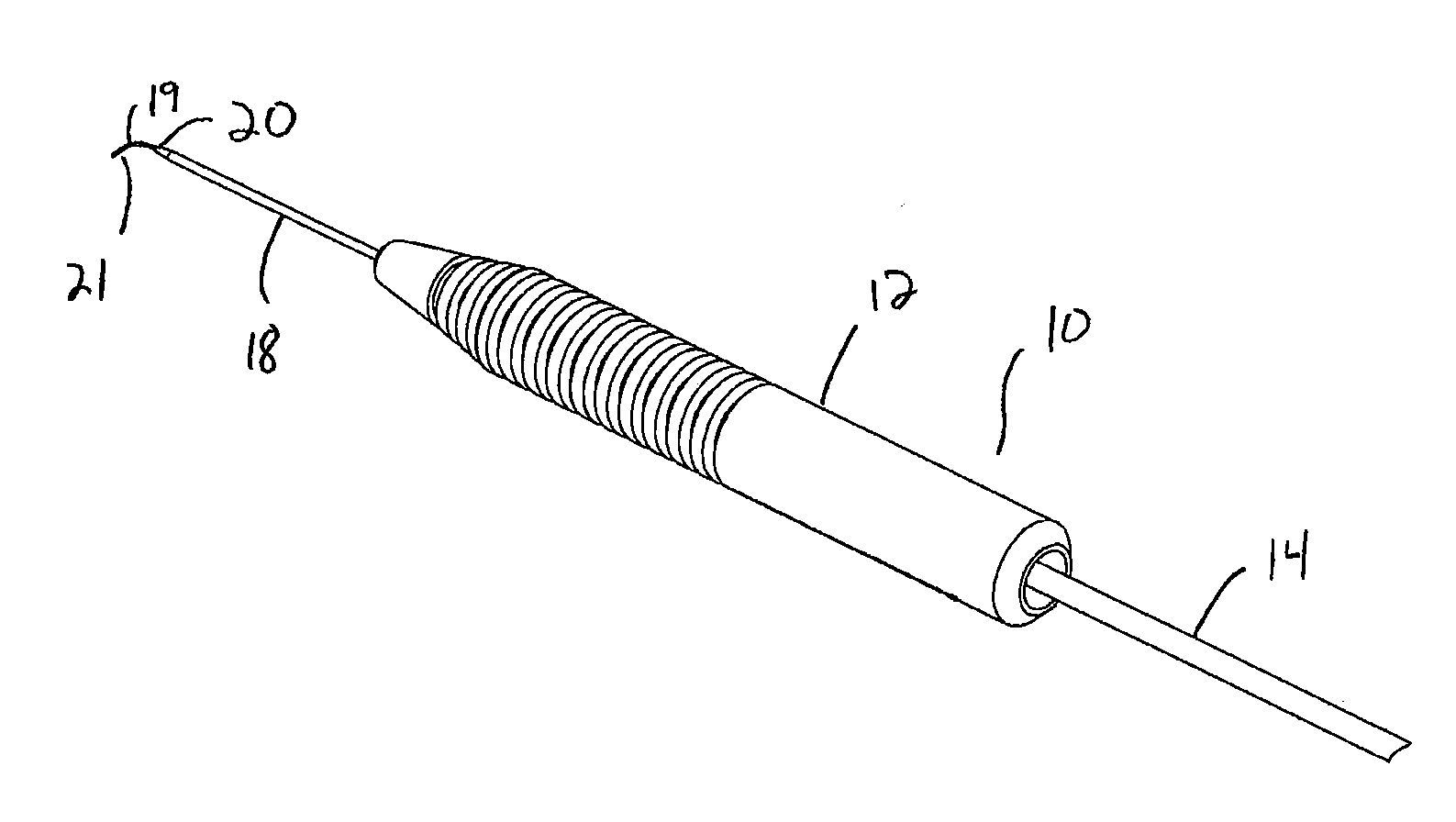
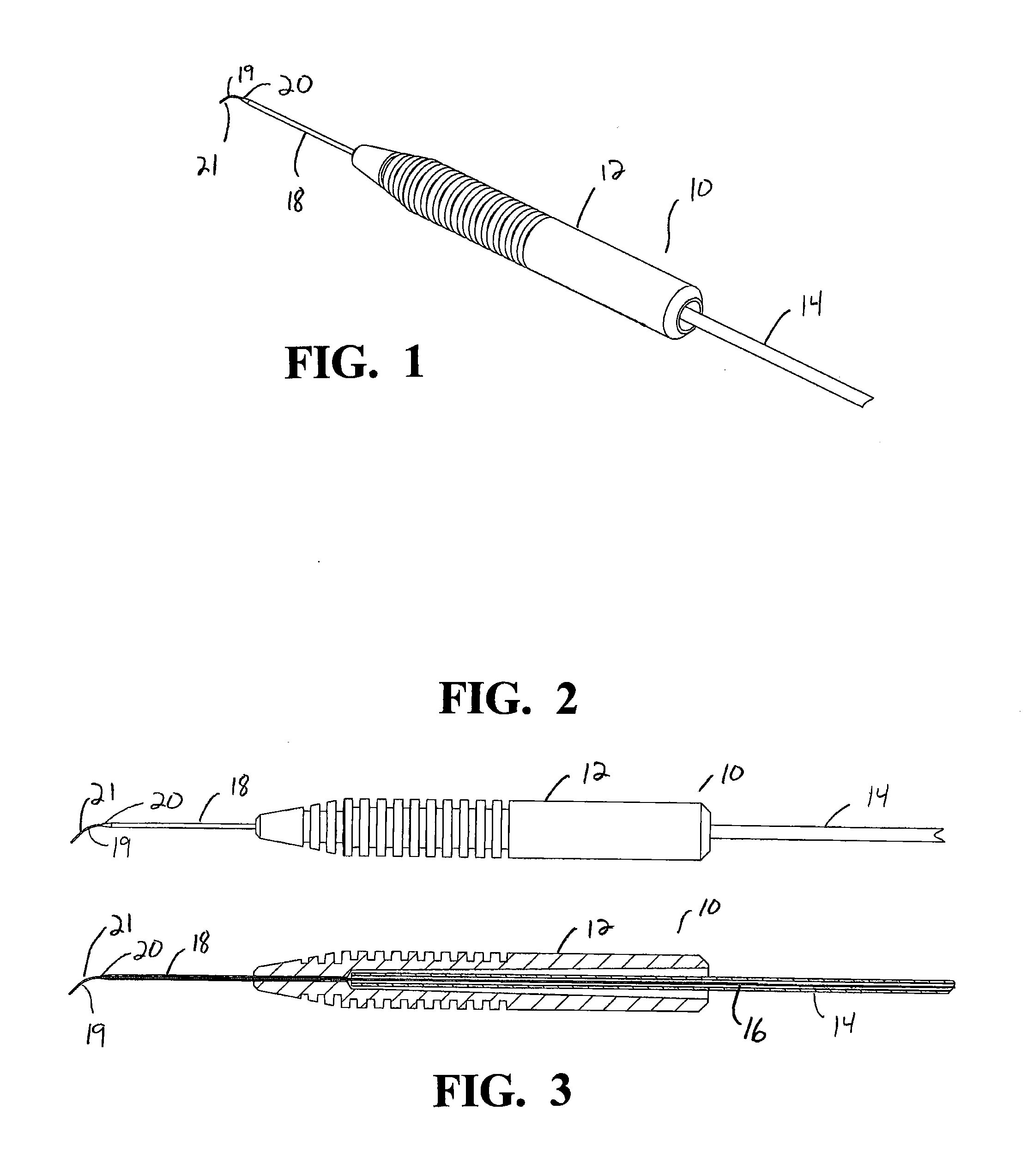
[0016]As best seen in the FIG. 1, probe 10 of the present invention generally consists of handle or body 12, containing or encasing fiber optic 16, flexible tube 19, distal cannula 18, and fiber optic sheath 14. Body 12 is generally hollow and can be made from any suitable material such as stainless steel, titanium or thermoplastic. Cannula 18 may be made from any suitable material such as titanium or stainless steel and held within body 12 by any conventional method, such as adhesive or crimping. Fiber optic sheath 14 may be any suitable tubing such as thermoplastic or silicone. Fiber optic 16 is connected on a proximal end (not shown) to any suitable laser or illumination source through a connector of a type well-known in the art and is surrounded by flexible tube 21 with exposed portion 19. Flexible tube 21 is made from a shape memory alloy such as Nitinol, and is held within cannula 18 by any conventional method, such as adhesive or crimping, and encases fiber optic 16, which is...


PUM


Abstract

A probe having a flexible, small diameter fiber sheathed in a small diameter flexible tube comprising the distal tip of the probe. The small diameters of the fiber and tube allow the fiber to be bent in a tighter radius along essentially the entire length of the exposed portion of the fiber, with low tube bending forces during insertion, providing a compact design which eliminates the need for a straight distal portion. The small diameter tube also allows a greater wall thickness outer cannula to be used, thereby increasing instrument rigidity. This compact, rigid design with low insertion forces allows the fiber greater access to the internal posterior structures of the eye, while providing increased instrument rigidity for manipulation of the eye, as well as low insertion forces.

Description

[0001]This invention relates to ophthalmic surgical equipment and more particularly to posterior segment ophthalmic surgical equipment.BACKGROUND OF THE INVENTION[0002]Microsurgical instruments typically are used by surgeons for removal of tissue from delicate and restricted spaces in the human body, particularly in surgery on the eye, and more particularly in procedures for removal of the vitreous body, blood, scar tissue, or the crystalline lens. Such instruments include a control console and a surgical handpiece with which the surgeon dissects and removes the tissue. With respect to posterior segment surgery, the handpiece may be a vitreous cutter probe, a laser probe, or an ultrasonic fragmenter for cutting or fragmenting the tissue and is connected to the control console by a long air-pressure (pneumatic) line and / or power cable, optical cable, or flexible tubes for supplying an infusion fluid to the surgical site and for withdrawing or aspirating fluid and cut / fragmented tissu...

Claims


Application Information

Patent Timeline
Patent Type & Authority Applications(United States)
IPC IPC(8): A61F9/007
CPCA61B19/5202A61B2017/00867A61B2019/5206A61F2009/00874A61F9/008A61F9/00821A61F2009/00863A61F9/007A61B90/30A61B2090/306
Inventor AULD, JACK R.ZICA, MICHAEL A.FARLEY, MARK
Owner ALCON INC
Why Eureka
Try Eureka