
Dynamic spine stabilization system

a spine stabilization and dynamic technology, applied in the field of spine stabilization systems, can solve the problems of reduced range of motion, reduced function, and reduced height of the intervertebral disc, and achieve the effect of stabilizing the spine parts

Inactive Publication Date: 2009-04-09
ZIMMER SPINE INC
View PDF103 Cites 137 Cited by
  • Summary
  • Abstract
  • Description
  • Claims
  • Application Information

AI Technical Summary

Benefits of technology

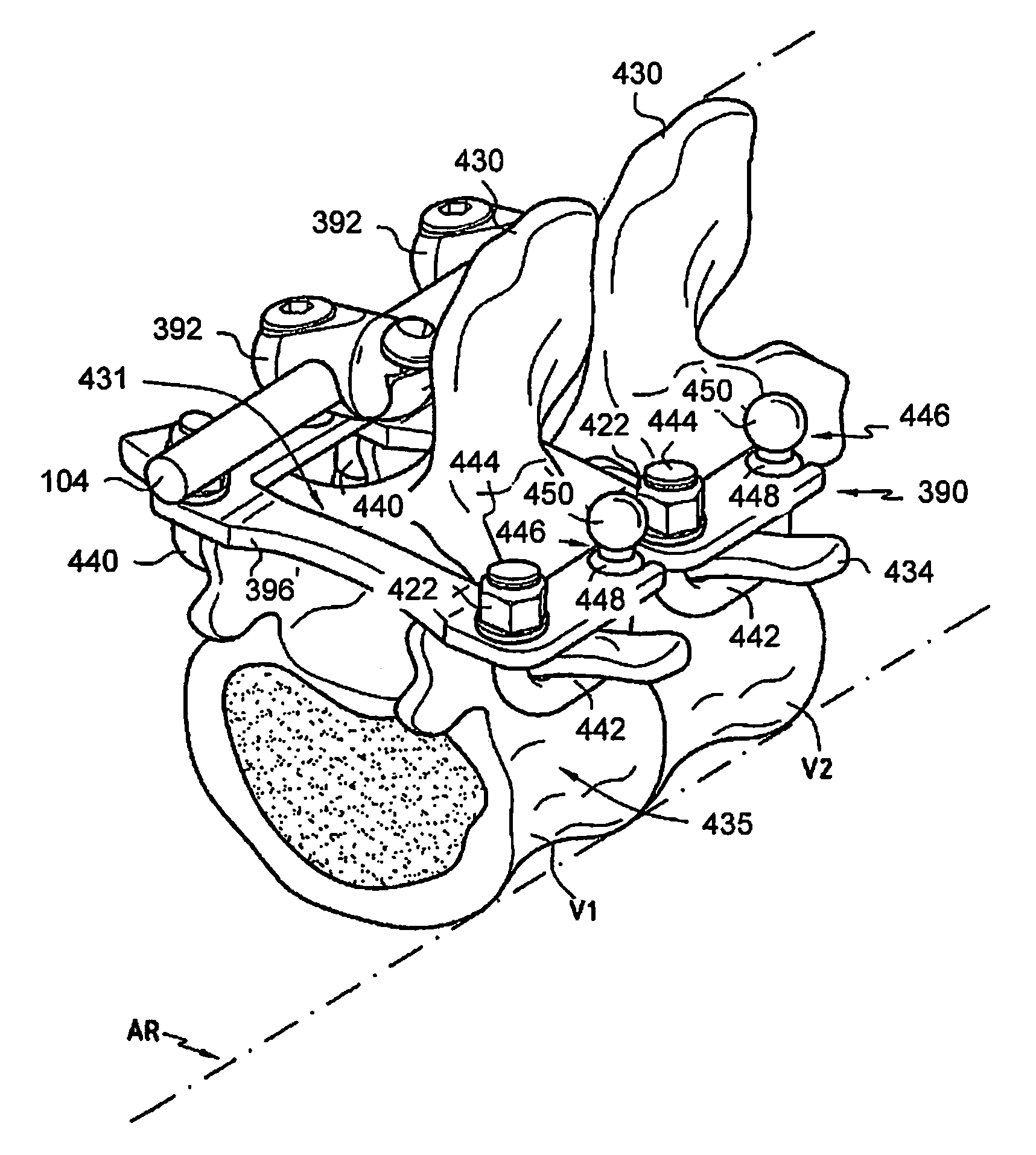
[0007]Embodiments of the present disclosure offer devices and systems for stabilizing portions of the spine. Furthermore, embodiments of the present disclosure may provide spinal stabilization utilizing the spinous processes. One embodiment may be directed to an interspinous member for stabilizing movement between adjacent vertebrae, including a body for stabilizing movement between a first spinous process and a second spinous process and two lateral portions extending from the body for engaging the two elongated members positioned lateral to the first spinous process and the second spinous process to stabilize movement between the elongated members. In some embodiments, the body may have a first surface for contact with an inferior portion of the first spinous process and a second surface for simultaneous contact with a superior portion of the second spinous process. In some embodiments, the upper surface has a curved portion for contact with a portion of the inferior portion of a spinous process. In some embodiments, the lower surface has a curved portion for contact with a portion of the superior portion of a spinous process. In some embodiments, each lateral portion is curved to receive a portion of an elongated member such that the lateral portion engages the elongated member. In some embodiments, each lateral portion comprises a receiving portion for receiving a portion of an elongated member.
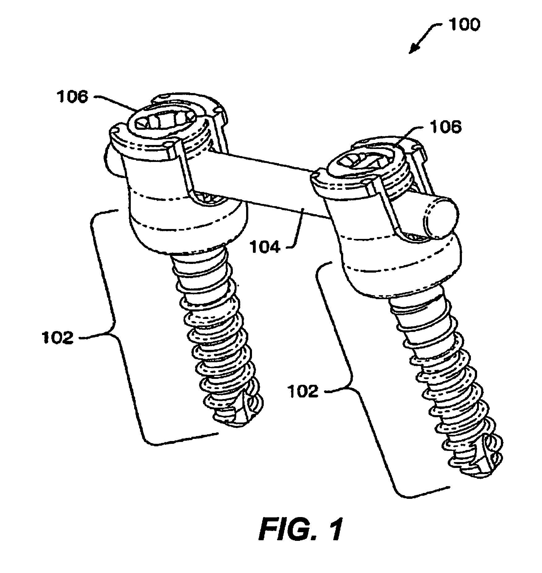
[0008]Another embodiment of the present disclosure is directed to a system for stabilizing movement between two or more vertebrae, including two elongated members for positioning lateral to two spinous processes of the vertebrae, two fasteners for coupling each elongated member to the vertebrae, and an interspinous member for coupling to the two elongated members for positioning between the spinal processes of adjacent spinous processes. In some embodiments, each interspinous member includes a body for stabilizing movement between a first spinous process and a second spinous process, having a first surface for contact with an inferior portion of the first spinous process and a second surface for simultaneous contact with a superior portion of the second spinous process, and two lateral portions extending from the body for engaging the two elongated members positioned lateral to the first spinous process and the second spinous process to stabilize movement between the elongated members. In some embodiments, positioning the lateral portions on the elongated members positions the body to stabilize movement between adjacent spinous processes. In some embodiments, a fastener comprises a bone fastener assembly. In some embodiments, a fastener comprises a hook. In some embodiments, a fastener comprises a bolt for passage through a portion of a spinous process. In some embodiments, a fastener comprises a clamp. In some embodiments, a fastener comprises a universal band. In some embodiments, the two elongated members are connected at both ends and comprise a slot along a portion thereof to accommodate two spinous processes. In some embodiments, a slot formed along a portion of a single rod divides the rod into two elongated members for positioning lateral to two spinous processes. In some embodiments, the two elongated members comprise an engagement feature, wherein one or more interspinous members engage the elongated members at one of the engagement features.
[0010]One advantage to implanting this type of system is the decreased number of bone fasteners, which may result in less time in surgery, decreased risk of damage to the spinal cord, spinal column, muscles, blood vessels, nerves, or other tissues or organs, and / or reduced recovery time, decreased complications such as pain or infection, or other surgical or subsequent issues.

Problems solved by technology

Injury or illness, such as spinal stenosis and prolapsed discs may result in intervertebral discs having a reduced disc height, which may lead to pain, loss of functionality, reduced range of motion, and the like.
It involves moderate to severe lateral curvature of the spine, and, if not treated, may lead to serious deformities later in life.

Method used


Image

  • Dynamic spine stabilization system
  • Dynamic spine stabilization system
  • Dynamic spine stabilization system

Examples


Embodiment Construction

[0041]The disclosure and the various features and advantageous details thereof are explained more fully with reference to the non-limiting embodiments that are illustrated in the accompanying drawings and detailed in the following description. Descriptions of well known starting materials, processing techniques, components and equipment are omitted so as not to unnecessarily obscure the disclosure in detail. Skilled artisans should understand, however, that the detailed description and the specific examples, while disclosing preferred embodiments of the disclosure, are given by way of illustration only and not by way of limitation. Various substitutions, modifications, additions or rearrangements within the scope of the underlying inventive concept(s) will become apparent to those skilled in the art after reading this disclosure.

[0042]A spinal stabilization system may be installed in a patient to stabilize a portion of a spine. Spinal stabilization may be used, but is not limited to...


PUM


Abstract

Disclosed are devices and systems for spinal fixation and dynamic stabilization. Elongated members may be positioned lateral to spinous processes and coupled to two or more vertebrae. Interspinous members may be positioned between adjacent spinous processes and coupled to the elongated members. One embodiment of an interspinous member comprises a body and two lateral portions. The lateral portions may couple to the elongated members to position the interspinous members. An interspinous member and the positioning of the interspinous member may allow selected movement between the adjacent spinous processes.

Description

TECHNICAL FIELD[0001]This disclosure relates generally to spinal implants and spine stabilization systems, and more particularly to apparatus and systems for stabilizing movement between spinous processes.BACKGROUND OF THE DISCLOSURE[0002]The human spine consists of segments known as vertebrae linked by intervertebral disks and held together by ligaments. There are 24 movable vertebrae—7 cervical, 12 thoracic, and 5 lumbar. Each vertebra has a somewhat cylindrical bony body (centrum), a number of winglike projections, and a bony arch. The bodies of the vertebrae form the supporting column of the skeleton. The arches are positioned so that the space they enclose forms the vertebral canal. It houses and protects the spinal cord, and within it the spinal fluid circulates. Ligaments and muscles are attached to various projections of the vertebrae.[0003]The spine is subject to abnormal curvature, injury, infections, tumor formation, arthritic disorders, and puncture or slippage of the ca...

Claims


Application Information

Patent Timeline
IPC IPC(8): A61B17/58A61B17/08A61B17/70A61B17/04
CPCA61B17/7011A61B17/7032A61B17/7037A61B17/7041A61B17/864A61B17/7047A61B17/7049A61B17/7053A61B17/707A61B17/7044
Inventor LEMOINE, JEREMY J.GRAY, WAYNEELY, KAMERON SCOTTPETERMAN, MARC M.
Owner ZIMMER SPINE INC
Learn More