
Process field device with augmented loop power and wireless communication

Inactive Publication Date: 2009-04-09
AIRSPRITE TECH
View PDF3 Cites 27 Cited by
  • Summary
  • Abstract
  • Description
  • Claims
  • Application Information

AI Technical Summary

Benefits of technology

[0010]In accordance with one embodiment of the present invention, a system for controlling and measuring a power source switches from a first source to a second source in rapid succession to help maintain function of a load during power transients. Fast switching is obtained by allowing each source to deliver current to the output load through a nonlinear device such as a Schottky diode. Power sources that have different characteristics in terms of capacity, reliability, temperature characteristics and schedule, for example, are configured to pump current through an inductive boost or buck power switching device. As the power sources switch modes, a signal is sent to a local controller that records the history of the energy delivered by the source in use. By using the history of the power delivered, the system anticipates switch points for enhanced power use among the available sources. The choice of the power source candidates is enabled through a predetermined setting, configured by an active controller algorithm. This algorithm, which is stored in temporary or permanent memory, determines the criteria under which the power extraction is sequenced. The method that determines the extraction criteria may or may not change over time, and operates in a way that helps provide continuous operation. This helps to provide proper data communications within the system and allows other nearby elements that contain additional historical data to share information relevant to the settings for enhanced energy management. In such cases, the temperature conditions, for example, may be known and made available by communicating to another device at a distant location, but within the system. Temperature can be a good predictor of energy supply performance and may be used to indicate the limits the power source. This and other environmental factors allow the wireless communicator to prepare for a power transient.

Problems solved by technology

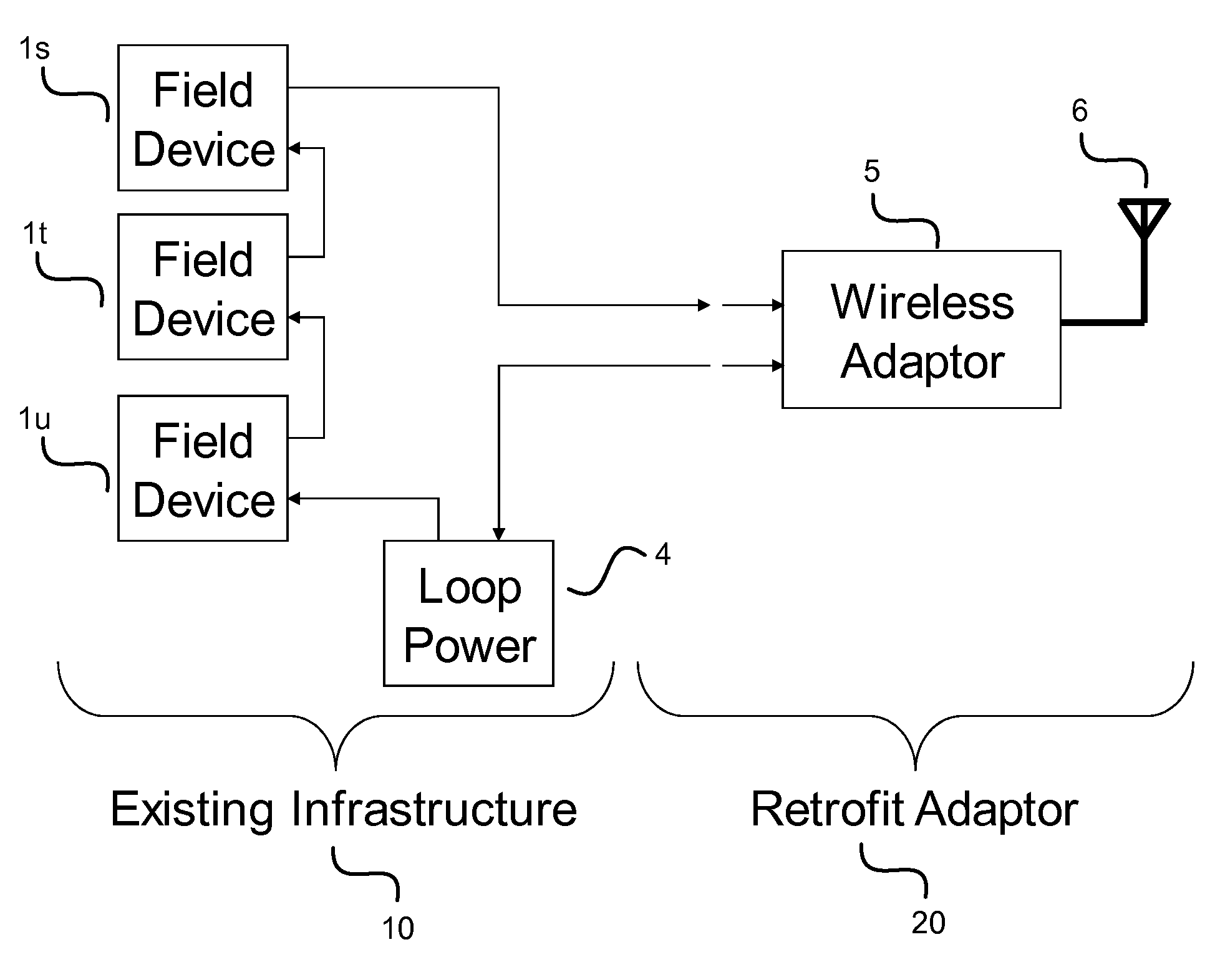
This is insufficient for use in a system that has a radio or other system component that uses more than 5.6 mW.
For example when a radio is transmitting at a power level of 10 dBm (10 mW) the power available is insufficient to enable sustained operation from loop power alone.

Method used


Image

  • Process field device with augmented loop power and wireless communication
  • Process field device with augmented loop power and wireless communication
  • Process field device with augmented loop power and wireless communication

Examples


Embodiment Construction

[0031]Aspects of the invention are described below with reference to illustrative embodiments. However, it should be understood that aspects of the invention are not limited to those embodiments described below, but instead may be used in any suitable system or arrangement.

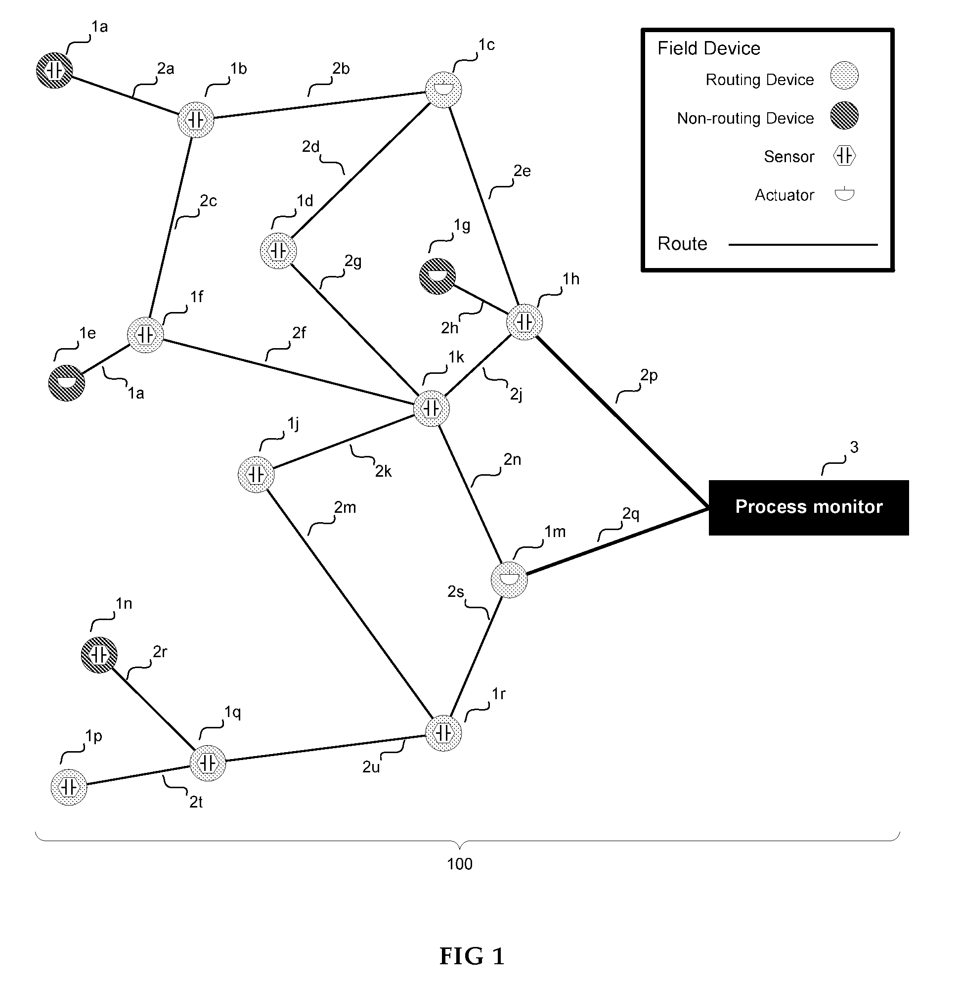
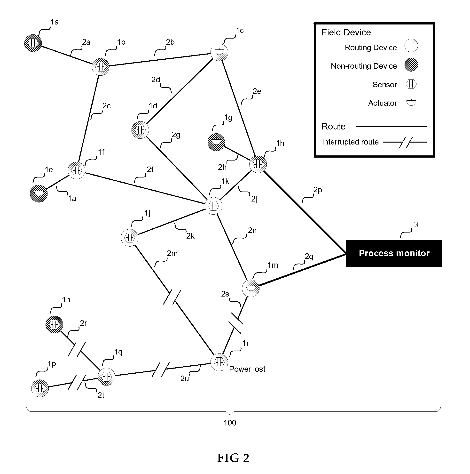
[0032]As illustrated in FIG. 1, aspects of the invention are described in relation to a process monitoring or process control system 100 (hereafter referred to as a process monitoring system 100), in which field devices 1 may be used to monitor and / or control industrial processes or other process, and in which data may be transmitted from the field devices 1 to a process monitor or process controller 3 (hereafter referred to as a process monitor 3). Routes 2 between a field device 1 and the process monitor 3 or between two field devices 1 may represent data transmission routes within the process monitoring system 100.

[0033]Aspects of the invention are also described in relation to a process monitoring system 100 i...


PUM


Abstract

A system for controlling and measuring a power source switches between a first source and a second source in rapid succession to help maintain function of a load. In particular, a primary source may be replaced or augmented by an auxiliary source. Fast switching is achieved by delivering current to the output load through a nonlinear device. A record of conditions when the power sources switch modes is maintained in memory. The record is used to anticipate subsequent mode switching events.

Description

CROSS-REFERENCE TO RELATED APPLICATIONS[0001]A claim of priority is made to U.S. Provisional Patent Application Ser. No. 60 / 977,389 entitled WIRELESS COMMUNICATION SYSTEM, filed Oct. 4, 2007, which is incorporated by reference.FIELD OF THE INVENTION[0002]This invention relates generally to industrial process control or monitoring systems, and more specifically to process field devices capable of wireless communication, such as radio frequency (RF) communication.BACKGROUND OF THE INVENTION[0003]In industrial settings, process control or monitoring systems may be used to control and / or monitor the parameters or outcomes of various industrial processes. Typically, a control or monitoring system uses field devices that are distributed at key locations in an industrial process and that have some connection to a remotely located process controller or process monitor. A field device may be any device that performs a distributed function in a process control or process monitoring system. Fi...

Claims


Application Information

Patent Timeline
IPC IPC(8): G06F1/26
CPCH02J1/10H02J17/00H02J7/34H02J50/001H02J50/40H02J50/80H02J50/10
Inventor MATTHEW, KERRY R.SHUMAKER, WAYNE G.MORAN, PATRICK J.
Owner AIRSPRITE TECH
Learn More