Crop Conditioning Roll With Herringbone Flutes Having A Radius

a crop conditioner and a radius technology, applied in the field of crop conditioner rolls, can solve the problems of affecting crop yield, affecting crop growth, and affecting crop growth, so as to reduce crop damage, eliminate crop cutting, and improve crop yield

Inactive Publication Date: 2009-04-16
DEERE & CO
View PDF28 Cites 4 Cited by
  • Summary
  • Abstract
  • Description
  • Claims
  • Application Information

AI Technical Summary

Benefits of technology

[0010]It is therefore an object of the invention to provide a herringbone fluted conditioning roll that avoids the problems set forth above with known conditioning rolls. More particularly, by twisting the flute to the roll and creating a large radius at the center, it is possible to greatly reduce crop damage in some crops and in most crops eliminate the cutting of crop in the center of the windrow. The large radius flute has a more positive feed to the crop than does the pointed flute type. It has also been found through FEA that the life of the roll is increased to a more satisfactory level when a large radius is added at the center of the roll.

Problems solved by technology

Rollers of this type tend to clutch and crack the crop rather vigorously.
A drawback to this configuration is that it does not operate smoothly and does not adequately squeeze out moisture continuously along the stems.
However, this type of configuration is not as effective as the above-described crimping method when it comes to feeding, grasping and clutching the stalks.
Such helical rolls have a tendency to load up crop materials along one side of the conditioned crop discharge flow from the rolls.
The resulting windrows or swaths may be less uniform than desired as a result, with heavier accumulations along one side than the other.
This can have an adverse effect upon drying times and hay quality.
However, a significant drawback of conditioner rolls having a herringbone type flute arrangement stems from the fact that in the known designs the herringbone pattern comes to a point at the center of the roll.
Testing with a herringbone fluted type conditioner roll with a point at center reveals problems with cut and chewed up crop at the center of the roll.
Tests further show that the point of the herringbone flute will cause crop hesitation resulting in cut crop.
It has also been found through finite element analysis (FEA) that the weld between flute segments at the roll center undergoes a significant amount of stress in operation and is a weak point in the construction of the roll, thus reducing the operational life of the roll to an unsatisfactory level.

Method used


Image

  • Crop Conditioning Roll With Herringbone Flutes Having A Radius
  • Crop Conditioning Roll With Herringbone Flutes Having A Radius
  • Crop Conditioning Roll With Herringbone Flutes Having A Radius

Examples


Embodiment Construction

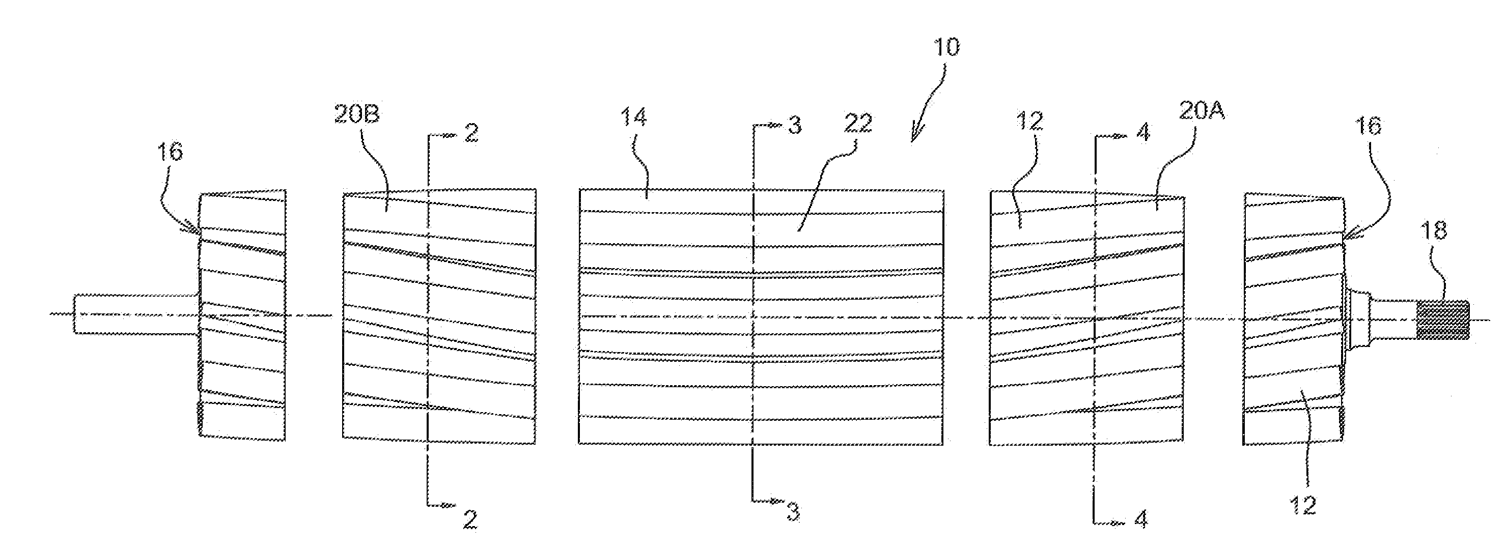
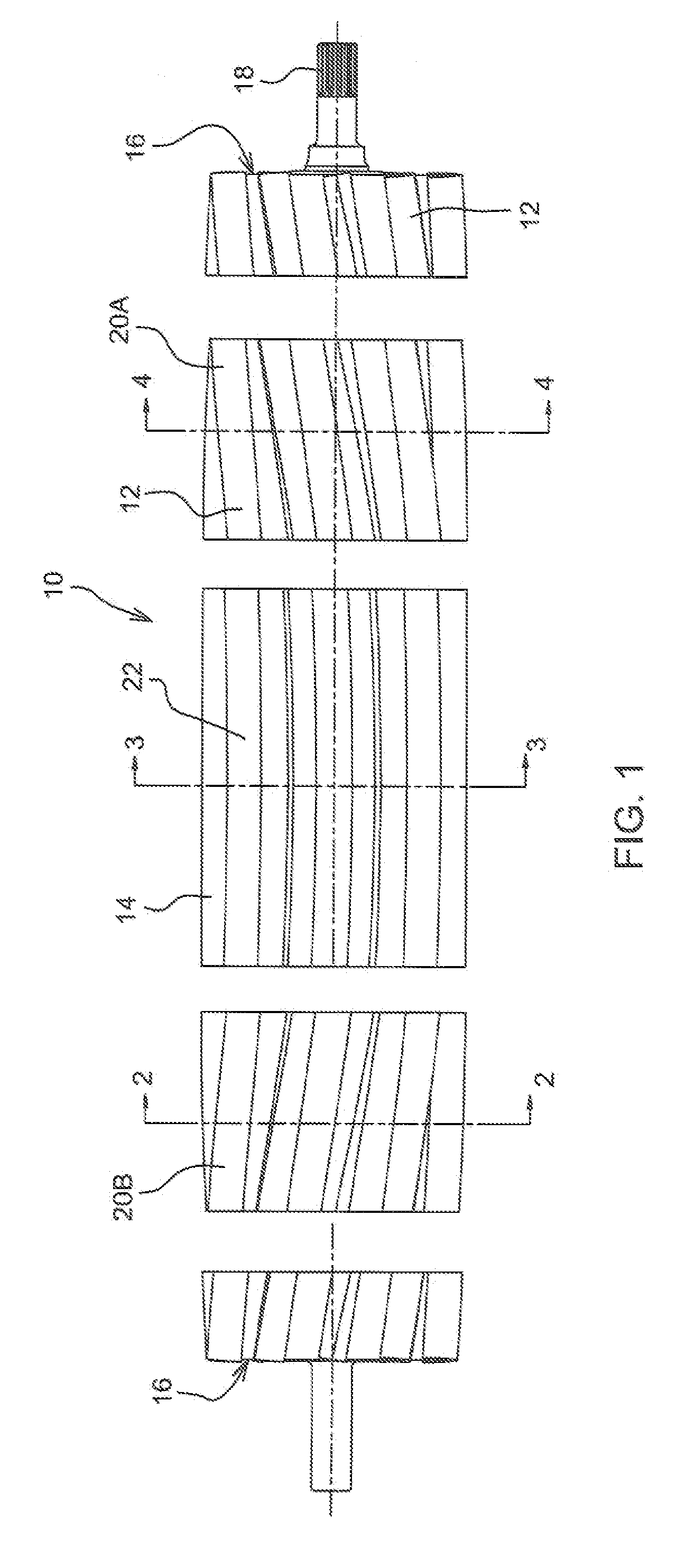
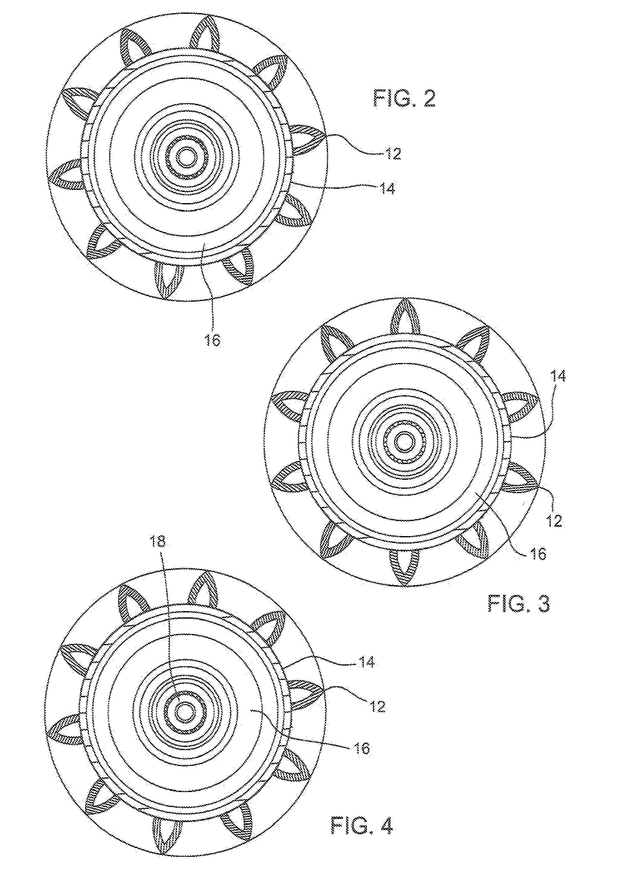
[0018]With reference to FIGS. 1-4 it can be seen that a metal conditioning roll 10 is illustrated having ribs 12 arranged in a herringbone pattern. Each herringbone roll 10 includes a cylindrical core 14 having a pair of opposite end plates 16 with stub shafts 18 projecting axially outwardly therefrom. Ten ribs 12 are spaced circumferentially around core 14 and project generally radially outwardly therefrom. In a preferred embodiment, each rib 12 is generally an ogival arch in transverse cross-section and hollow, although other configurations such as solid, transversely rectangular or triangular bars may also be utilized. Each rib 12 extends longitudinally of core 14 over its entire length. One segment 20a extends generally helically about core 14 in a right-hand spiral toward apex 22, while the other segment 20b extends helically around core 14 in a left-hand spiral from apex 22. The two rib segments 20 converge from opposite ends of core 14 toward apex 22.

[0019]Those having skill ...


PUM


Abstract

The conditioning rolls of a crop harvester have intermeshing metal ribs arranged in a herringbone pattern, each rib comprising a pair of end-to-end segments that converge spirally from opposite ends of the roll to a centermost radius.

Description

CROSS-REFERENCE TO RELATED APPLICATION [0001]This application claims priority form U.S. Provisional Patent Application 60 / 979,265 filed on 11 Oct. 2007.FIELD OF THE INVENTION [0002]This invention relates to an improved crop conditioner roll such as is used in an agricultural mower-conditioner or the like.BACKGROUND OF THE INVENTION [0003]In agriculture there is a widely known practice known as “hay conditioning” wherein the drying of mowed hay crops in the field is hastened, with a resulting reduction in weather damage, by a crushing of the crop stems. This operation substantially reduces the length of time required for drying of the stems roughly to the same length of time required for drying of the leaves, thereby reducing the overall harvesting time while simultaneously producing an improved crop. A known means for accomplishing this function is to provide two pressure rolls that are driven in opposite directions of rotation so that mowed crop stalks are grasped and passed betwee...

Claims


Application Information

Patent Timeline
Patent Type & Authority Applications(United States)
IPC IPC(8): A01D82/02
CPCA01D82/02
Inventor ROSENBALM, ALLAN W.EUBANKS, JASON C.SLOAN, CHARLES S.SMITH, DAVID C.
Owner DEERE & CO
Why Eureka
Try Eureka