Water drift compensation method and device

a compensation method and technology of water drift, applied in the direction of steering initiation, navigation instruments, instruments, etc., can solve the problems of large watch circle errors, large variations in the location of objects being moored, and cost and difficulty in deploymen

Inactive Publication Date: 2009-04-16
CARDOZA MIGUEL ANGEL +4
View PDF5 Cites 23 Cited by
  • Summary
  • Abstract
  • Description
  • Claims
  • Application Information

AI Technical Summary

Problems solved by technology

There are several problems with mooring systems, particularly when utilizing such methods in deep water.
Mooring systems engineered for deep water must be of a physical size, weight, and complexity which makes them costly and difficult to deploy.
Furthermore, long mooring cables lead to large variations in the location of the object being moored.
For applications where precise object placement is required, large watch circle errors can be problematic.
Still further, mooring systems require time to prepare and deploy, and thus are not effective for portable applicatio

Method used


Image

  • Water drift compensation method and device
  • Water drift compensation method and device
  • Water drift compensation method and device

Examples


first embodiment

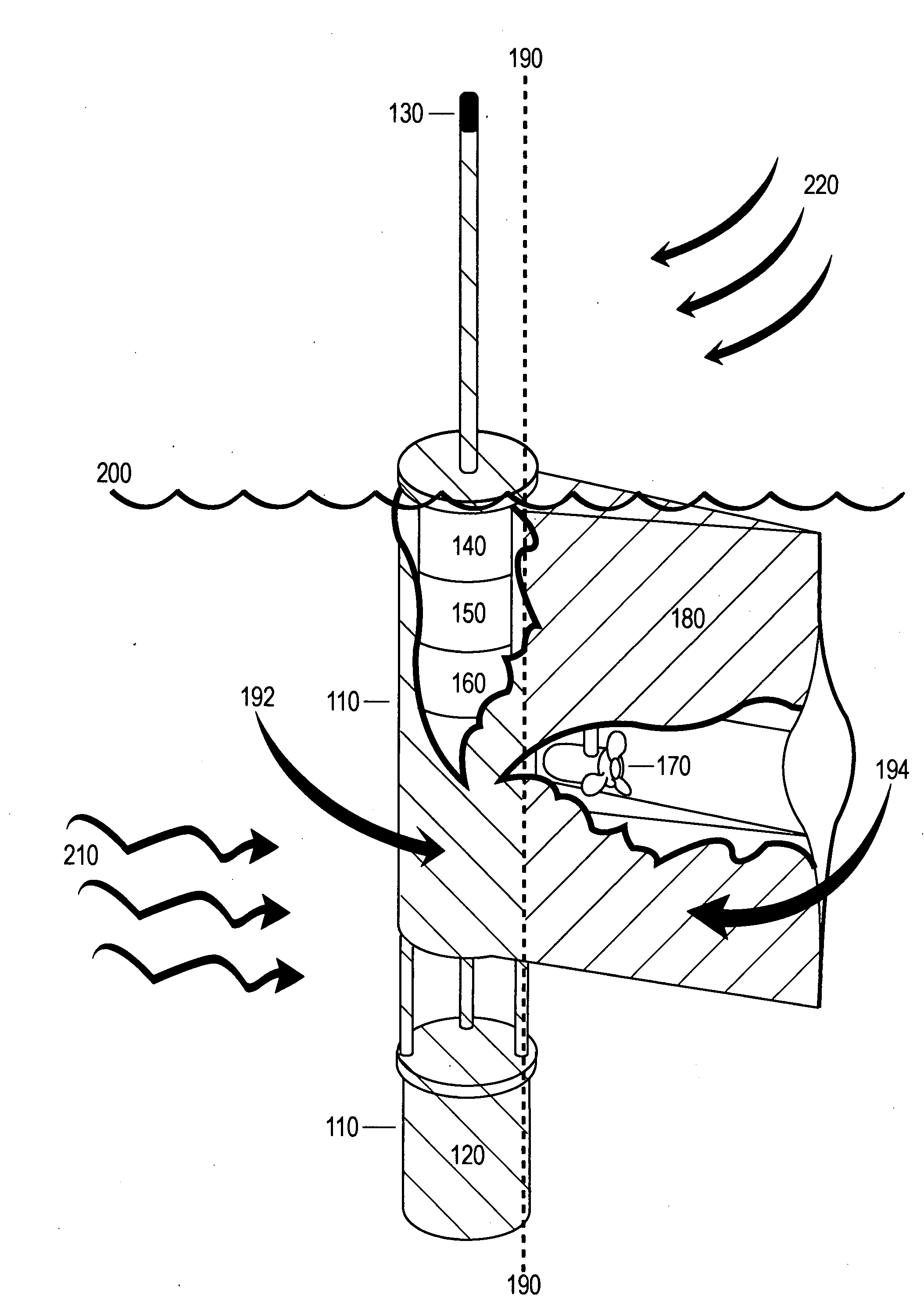
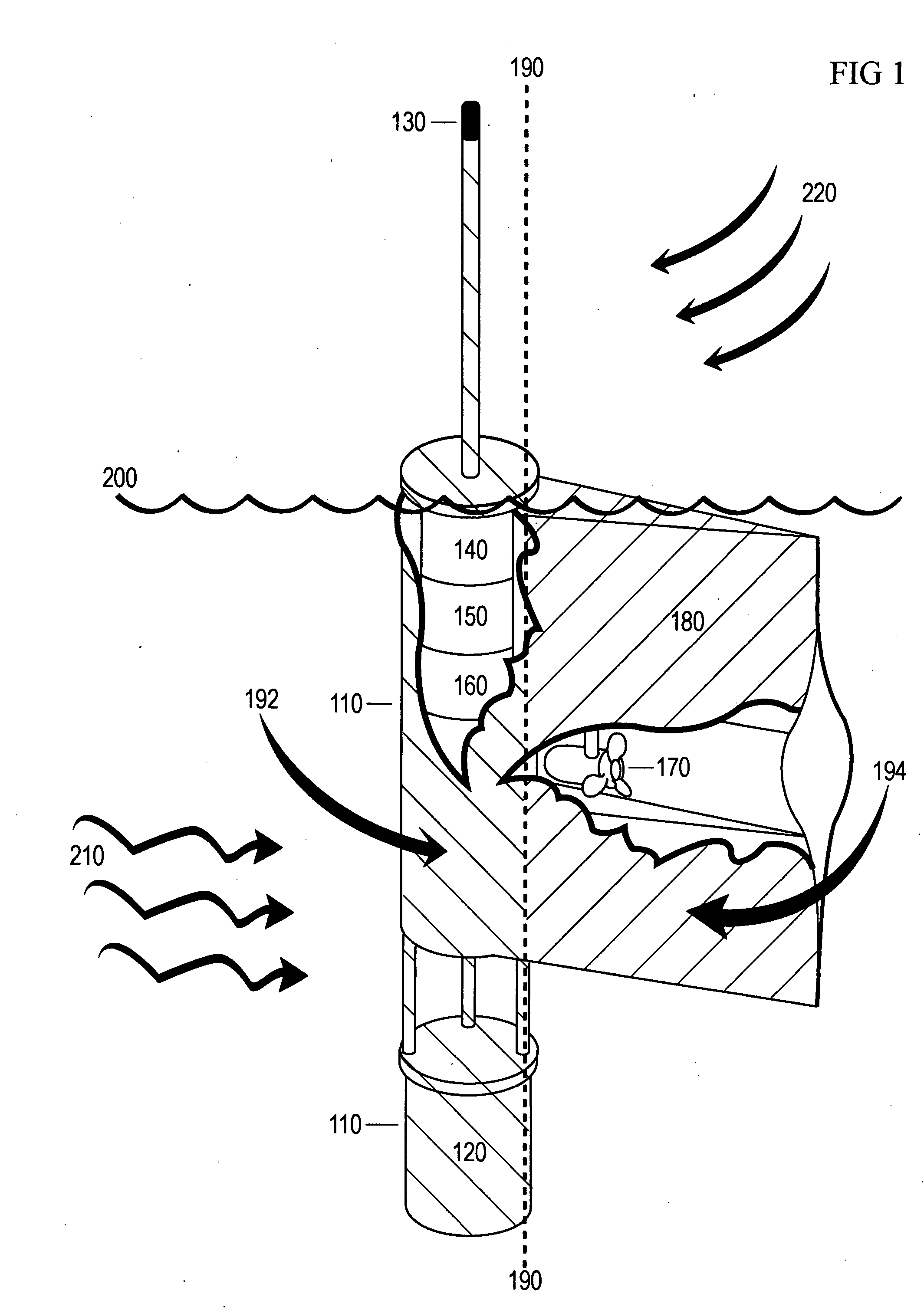
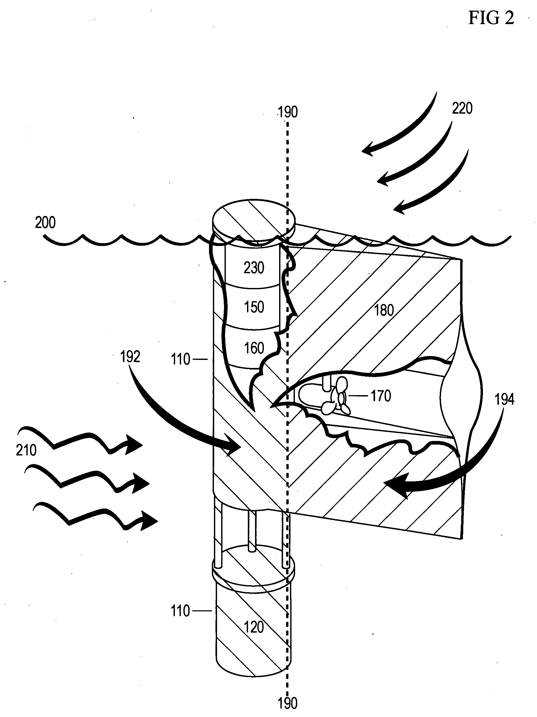
[0017]One embodiment of the device is illustrated in FIG. 1. The device includes a water-tight enclosure 110 for electronics instrumentation and the same or similar water-tight enclosure 110 for a power source, such as one or more batteries 120. The device provides sufficient surface area to install a GPS antenna 130 for receiving the radio frequency signals transmitted by the GPS satellite system. The GPS antenna is connected to a GPS navigation receiver 140 located within the water-tight enclosure.

[0018]The GPS navigation receiver is connected to a computer processor 150 located within the water-tight enclosure. The computer processor is connected to a motor controller 160 located within the water-tight enclosure. The motor controller is connected through a water-tight connector to one or more motors, thrusters, or other means of water propulsion 170 located outside the water-tight enclosure. The water-tight enclosure and propulsion system are attached to a hydrofoil 180.

[0019]The...


PUM


Abstract

Current methods for station keeping an object in the ocean or body of water involve mooring assemblies or active and complex navigation and differential thrust or thrust and rudder assemblies. The embodiments herein provide a method and device for compensating for the force of water or ocean currents through the use of a hydrofoil assembly to orient a device in the water current direction, through the use of any number of devices for sensing water current force, and through the use of a motor assembly to produce sufficient thrust to compensate for water current drift. An alternate embodiment allows the method to be employed without sensing the force of the water current. The method does not require directional thrust or active rudder assemblies, is highly portable, utilizes minimal power, is light weight, is scalable, and can be operated in any body of water.

Description

CROSS-REFERENCE TO RELATED APPLICATIONS[0001]This application claims benefit of PPA Ser. No. 60 / 917,432, filed May 11, 2007 by the present inventors, which is incorporated by reference.FEDERALLY SPONSORED RESEARCH[0002]Not Applicable SEQUENCE LISTING OR PROGRAM[0003]Not ApplicableBACKGROUND OF THE INVENTION[0004]1. Field of Invention[0005]Embodiments presented herein generally relate to a method or process of compensating for the position or location displacement caused by the force of water or ocean current. More specifically, embodiments relate to a device that compensates for this force by utilizing the force of the water current to orient the means of compensation.[0006]2. Prior Art[0007]The force of an ocean or water current will alter the position or location of an object. The amount of the resulting displacement is a function of the magnitude of the force of the water current and the cross sectional area and coefficient of drag of the object. Previously the means for reducing...

Claims


Application Information

Patent Timeline
IPC IPC(8): B63H25/42G05D1/02G01C21/00B43L9/02
CPCB63H25/42G05D1/0208G01C21/00
Inventor CARDOZA, MIGUEL ANGELADAMEZ, WILLIAM ANDREWTOMLINSON, DEVIN MORGANBENEDICT, SARAH ANNWOLF, MARK HENRY
Owner CARDOZA MIGUEL ANGEL
Why Eureka
Try Eureka