Eureka AIR delivers breakthrough ideas for toughest innovation challenges, trusted by R&D personnel around the world.

Differential poly doping and circuits therefrom

Active Publication Date: 2009-04-16
TEXAS INSTR INC
View PDF3 Cites 5 Cited by
  • Summary
  • Abstract
  • Description
  • Claims
  • Application Information

AI Technical Summary

Benefits of technology

[0017]A CMOS integrated circuit comprises a substrate having a semiconductor surface, a gate dielectric layer on the semiconductor surface and a plurality of polysilicon gates and a plurality of polysilicon lines on the gate dielectric layer the polysilicon gates and lines in a first region of the circuit have a lower dose of a first dopant type as compared to the polysilicon gates and lines in a second region of said circuit which have at least a 20% higher dose of the first dopant type. The circuit includes a plurality of PMOS devices including respective ones of the

Problems solved by technology

As a result, the SRAM PMOS load transistors can suffer an increase in TOXINV, resulting in performance degradation including IDSAT.
Variation of SRAM load transistor performance in a cell can also increase substantially, leading to degraded cell stability and possible impairment in function.
Regarding SRAMs, scaling is known to degrade stability.
In the 6T cell, for example, counterdoping can cause imbalance in the pMOS load transistors, leading to degraded stability and may be unstable enough to not be able to retain the desired bit state, during either or both the read or write operations.

Method used


Image

  • Differential poly doping and circuits therefrom
  • Differential poly doping and circuits therefrom
  • Differential poly doping and circuits therefrom

Examples


Embodiment Construction

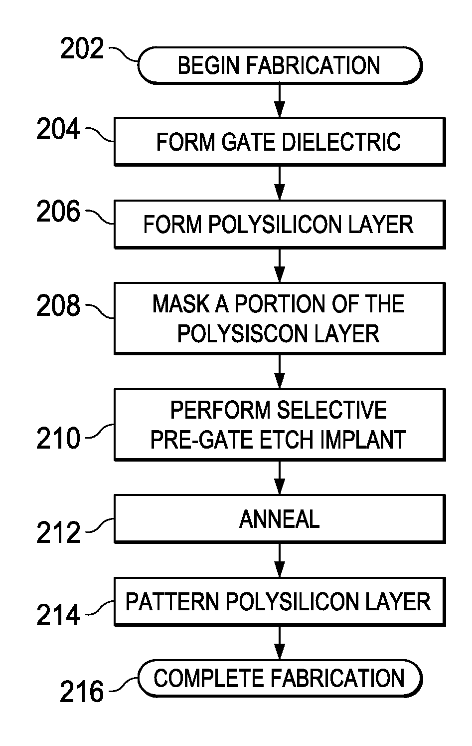
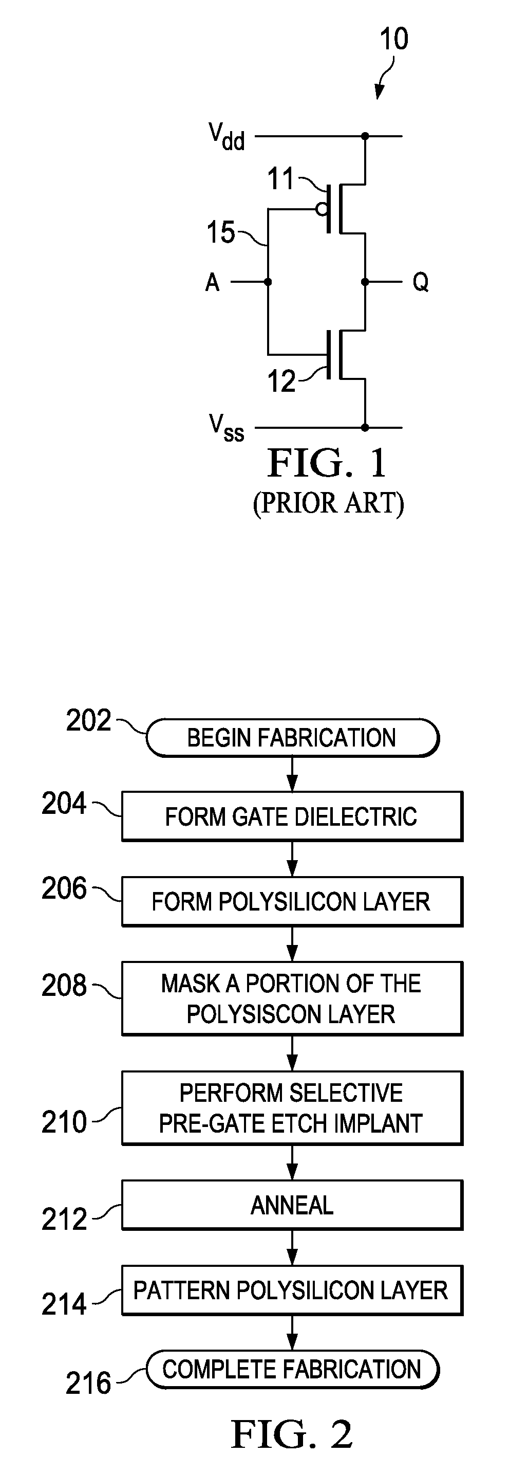
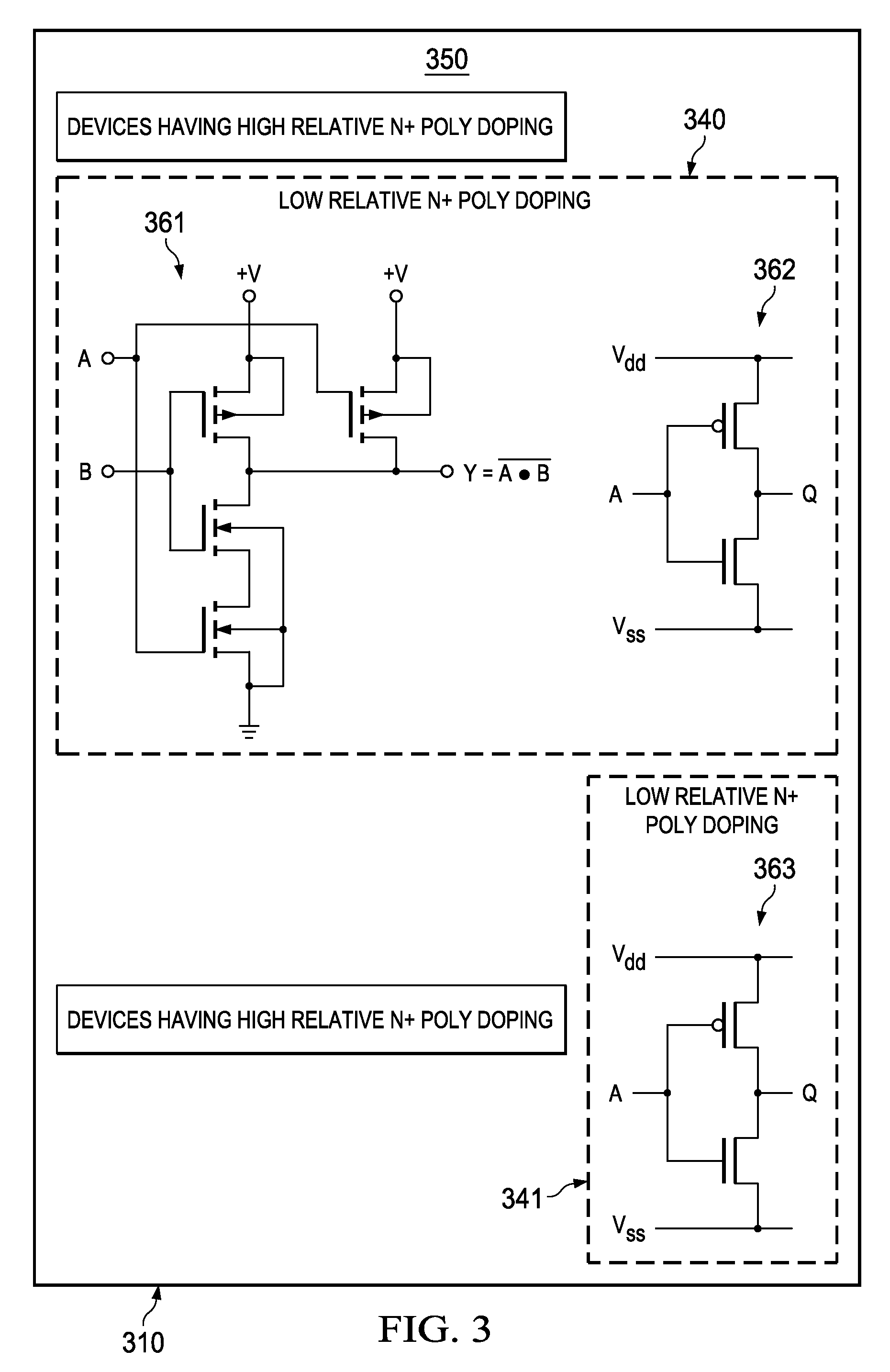
[0023]The present invention is described with reference to the attached figures, wherein like reference numerals are used throughout the figures to designate similar or equivalent elements. The figures are not drawn to scale and they are provided merely to illustrate the instant invention. Several aspects of the invention are described below with reference to example applications for illustration. It should be understood that numerous specific details, relationships, and methods are set forth to provide a full understanding of the invention. One having ordinary skill in the relevant art, however, will readily recognize that the invention can be practiced without one or more of the specific details or with other methods. In other instances, well-known structures or operations are not shown in detail to avoid obscuring the invention. The present invention is not limited by the illustrated ordering of acts or events, as some acts can occur in different orders and / or concurrently with o...


PUM


Abstract

A method of fabricating a CMOS integrated circuit and integrated circuits therefrom includes the steps of providing a substrate having a semiconductor surface, forming a gate dielectric layer on the semiconductor surface and a polysilicon including layer on the gate dielectric. A portion of the polysilicon layer is masked, and pre-gate etch implant of a first dopant type into an unmasked portion of the polysilicon layer is performed, wherein masked portions of the polysilicon layer are protected from the first dopant. The polysilicon layer is patterned to form a plurality of polysilicon gates and a plurality of polysilicon lines, wherein the masked portion includes at least one of the polysilicon lines which couple a polysilicon gate of a PMOS device to a polysilicon gate of an NMOS device. Fabrication of the integrated circuit is then completed, wherein the integrated circuit includes at least one first region formed in the masked portion lacking the first dopant in the polysilicon gates from the pre-gate etch implant and at least one second region formed in the unmasked portion having the first dopant in the polysilicon gates from the pre-gate etch implant.

Description

FIELD OF INVENTION[0001]The present invention relates generally to semiconductor processing, and more particularly to CMOS processing flows and devices therefrom which utilize doping differentials to improve circuit performance.BACKGROUND[0002]An n+ poly pre-gate doping mask has traditionally been used to achieve dopant levels above levels provided by the n+ source / drain implant in n-doped polysilicon to improve NMOS transistor performance in CMOS integrated circuits. In such a flow, following polysilicon deposition, an n-poly pre-gate etch doping mask is used for protecting / covering the poly regions corresponding to the PMOS gate area, and n-type dopant (e.g. P or As) is implanted into the polysilicon layer corresponding to the NMOS gate area. An optional dopant anneal may follow the n+ poly pre-gate etch implant to activate the dopant. A gate etch step then follows to define the n-type and p-type doped polysilicon gates for the respective NMOS and PMOS transistors.[0003]As known i...

Claims


Application Information

Patent Timeline
IPC IPC(8): H01L27/11H01L21/3205
CPCG11C11/412H01L21/26513H01L27/0922H01L21/32155H01L21/823842H01L21/28052Y10S257/903
Inventor EKBOTE, SHASHANKBENAISSA, KAMELBALDWIN, GREG C.OBRADOVIC, BORNA
Owner TEXAS INSTR INC
Why Eureka
Eureka Blog
Learn More