
Driving control apparatus and method for linear compressor

a linear compressor and control apparatus technology, applied in the field of compressors, can solve the problems that the reciprocating compressor cannot be operated with the maximum stroke and the reciprocating compressor cannot be operated at the maximum compression volum

Active Publication Date: 2009-04-16
LG ELECTRONICS INC
View PDF5 Cites 18 Cited by
  • Summary
  • Abstract
  • Description
  • Claims
  • Application Information

AI Technical Summary

Benefits of technology

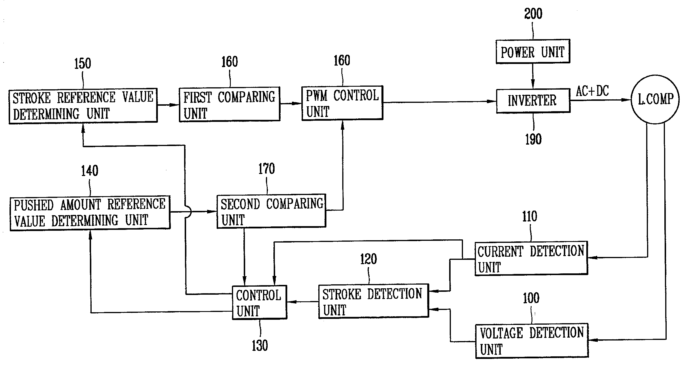
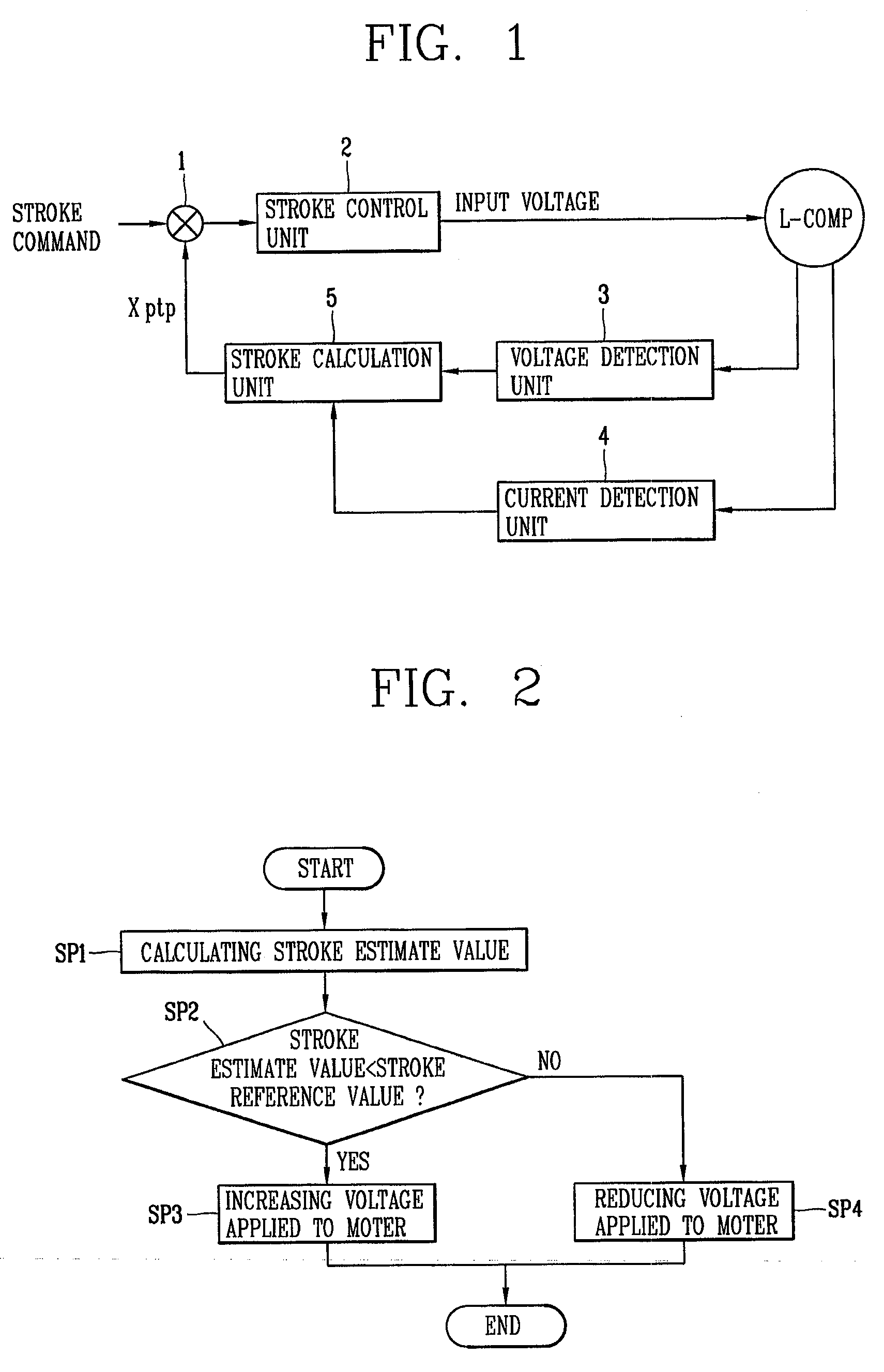
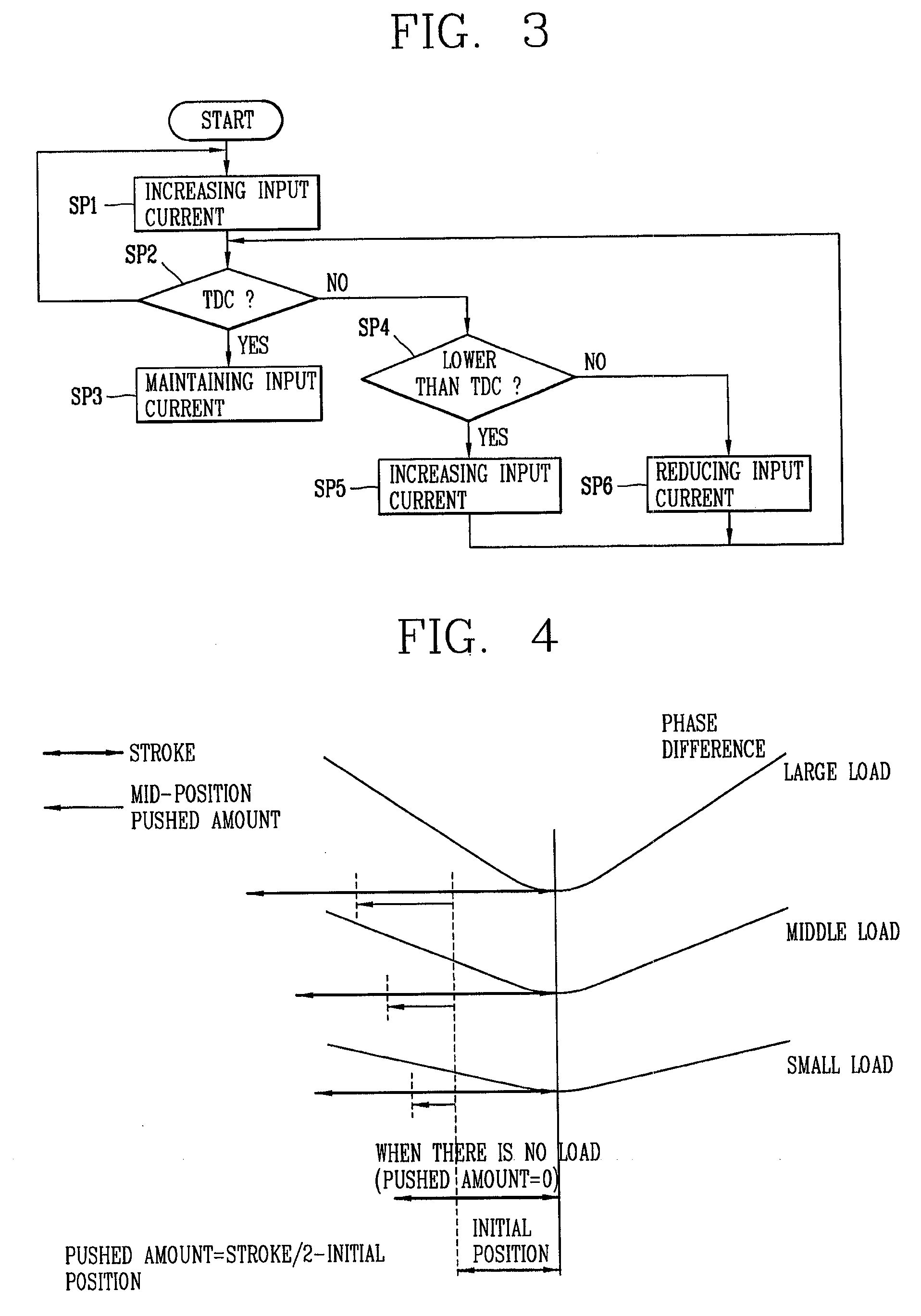
The present invention provides an apparatus and method for controlling the operation of a reciprocating compressor. The apparatus includes a control unit for detecting the current pushed amount of a piston when a TDC is detected, comparing it with a pushed amount reference value, and applying a DC voltage to a linear motor based on the comparison result. This allows for a maximum compression volume without collision of the piston. The method includes increasing stroke by adding an AC voltage and a DC voltage to the linear motor, detecting TDC, maintaining the current AC voltage, detecting the current stroke, calculating the pushed amount, and varying the DC voltage based on the comparison result. The technical effects of the invention include increasing the efficiency of the compressor and achieving a stable compression volume.

Problems solved by technology

However, when a gas spring constant is small, the reciprocating compressor cannot be operated with the maximum stroke without collision of the piston because a pushed amount of the piston is small.
That is, the reciprocating compressor cannot be operated at the maximum compression volume.

Method used


Image

  • Driving control apparatus and method for linear compressor
  • Driving control apparatus and method for linear compressor
  • Driving control apparatus and method for linear compressor

Examples


Embodiment Construction

[0047]An apparatus and method for controlling an operation of a reciprocating compressor by which stroke is increased by applying an AC voltage and a DC voltage to a linear motor, and when a top dead center (TDC) is detected, a current pushed amount is calculated and compared with a pushed amount reference value, and the DC voltage or a DC current applied to the linear motor is varied based on the comparison result to thereby obtain a maximum compression volume stably without collision of a piston, according to preferred embodiments of the present invention will now be described.

[0048]In the apparatus and method for controlling an operation of a reciprocating compressor, the present invention considers that, as shown in FIG. 4, because a pushed amount increases in proportion to a size of a load, a maximum compression volume can be obtained without collision of a piston by compensating the pushed amount with a DC voltage or a DC current.

[0049]FIG. 5 is a schematic block diagram showi...


PUM


Abstract

An apparatus for controlling an operation of a reciprocating compressor, includes: a control unit for detecting a current pushed amount of a piston when a TDC is detected as an inflection point of a phase difference between stroke and current, comparing the current pushed amount with a pushed amount reference value, and applying a DC voltage applied to a linear motor based on the comparison result. An AC voltage and a DC voltage are applied to the linear motor to increase the stroke, and when the TDC is detected, the current pushed amount is calculated and compared with the pushed amount reference value, and then, the DC voltage or a DC current applied to the linear motor is varied based on the comparison result, thereby obtaining a maximum compression volume without collision of the piston.

Description

BACKGROUND OF THE INVENTION[0001]1. Field of the Invention[0002]The present invention relates to a compressor and, more particularly, to an apparatus and method for controlling an operation of a reciprocating compressor.[0003]2. Description of the Related Art[0004]In general, a reciprocating compressor is operated to suck, compress and discharge a refrigerant gas by reciprocally and linearly moving a piston in a cylinder provided therein.[0005]The reciprocating compressor is divided into a compressor using a recipro method and a compressor using a linear method according to how the piston is driven.[0006]In the compressor using the recipro method, a crank shaft is coupled with a rotary motor and the piston is coupled with the crank shaft in order to change a rotating force of the rotary motor to a reciprocating motion.[0007]In the compressor using the linear method, the piston connected with an actuator of a linear motor is linearly moved.[0008]The reciprocating compressor using the...

Claims


Application Information

Patent Timeline
Patent Type & Authority Applications(United States)
IPC IPC(8): F04B49/06H02P25/06
CPCH02P25/027F04B35/045F04B49/065F04B49/12F04B2201/0206F04B2203/0401F04B2203/0402H02P25/06H02P25/032F04B35/04F04B2207/046H02P25/062
Inventor SUNG, JI-WONYOO, JAE-YOOHEO, KYUNG-BUM
Owner LG ELECTRONICS INC
Learn More