Abrasive-recovery mechanism in blasting machine

a technology of abrasive recovery and blasting machine, which is applied in the direction of abrasive machine accessories, metal-working equipment, manufacturing tools, etc., can solve the problems of contaminated working environment, difficult to transport workpieces up into and down from the blasting chamber, and large renovation of the floor, etc., to achieve the effect of reducing the size of the entire blasting machine, low cost and easy elimination

Active Publication Date: 2009-04-16
FUJI MFG CO LTD
View PDF9 Cites 29 Cited by
  • Summary
  • Abstract
  • Description
  • Claims
  • Application Information

AI Technical Summary

Benefits of technology

[0032]Furthermore, a plurality of introduction conduits 31 for introducing external air into the recovery pipe 30 can be provided at regular intervals in the length direction of the recovery pipe 30 to eliminate any abrasive clogging the recovery pipe 30.
[0045]In the structure where sucking is carried out for the recovery pipe of each recovery unit 18 or for the recovery pipes of a predetermined number of recovery units, the sizes of the duct, cyclone, dust collector, blower, and so forth can be reduced, compared with a case where sucking is carried out for all the recovery pipes 30 simultaneously. Because of this, the size of the entire blasting machine can also be reduced. Furthermore, this type of the abrasive-recovery mechanism can be provided at low cost.

Problems solved by technology

During the process of ejecting powders or particles onto a workpiece in this manner, the working environment is contaminated by any dispersion of the reusable abrasive that has been recovered after being ejected, the crushed abrasive particle as a result of the abrasive bombarding on the workpiece, or dust such as a cut particle of the workpiece.
However, if a blasting machine has the above-described structure and needs to process a large workpiece W, there is no choice but to make the blasting machine itself larger, thus also making the hopper 10′ larger.
This makes it difficult to transport the workpiece W up into and down from the blasting chamber 2.
This approach, however, is not only money- and labor-consuming in installing the blasting machine 1 but also requires extensive renovation of the floor, the base, and so forth of the existing building.
In short, this approach is difficult to adopt for existing buildings.
This makes the overall machine large and increases the cost of the machine.

Method used


Image

  • Abrasive-recovery mechanism in blasting machine
  • Abrasive-recovery mechanism in blasting machine
  • Abrasive-recovery mechanism in blasting machine

Examples


Embodiment Construction

[0057]Embodiments according to the present invention will now be described with reference to the drawings. However, the present invention is not limited to the examples depicted in the drawings.

Overall Structure of Blasting Machine

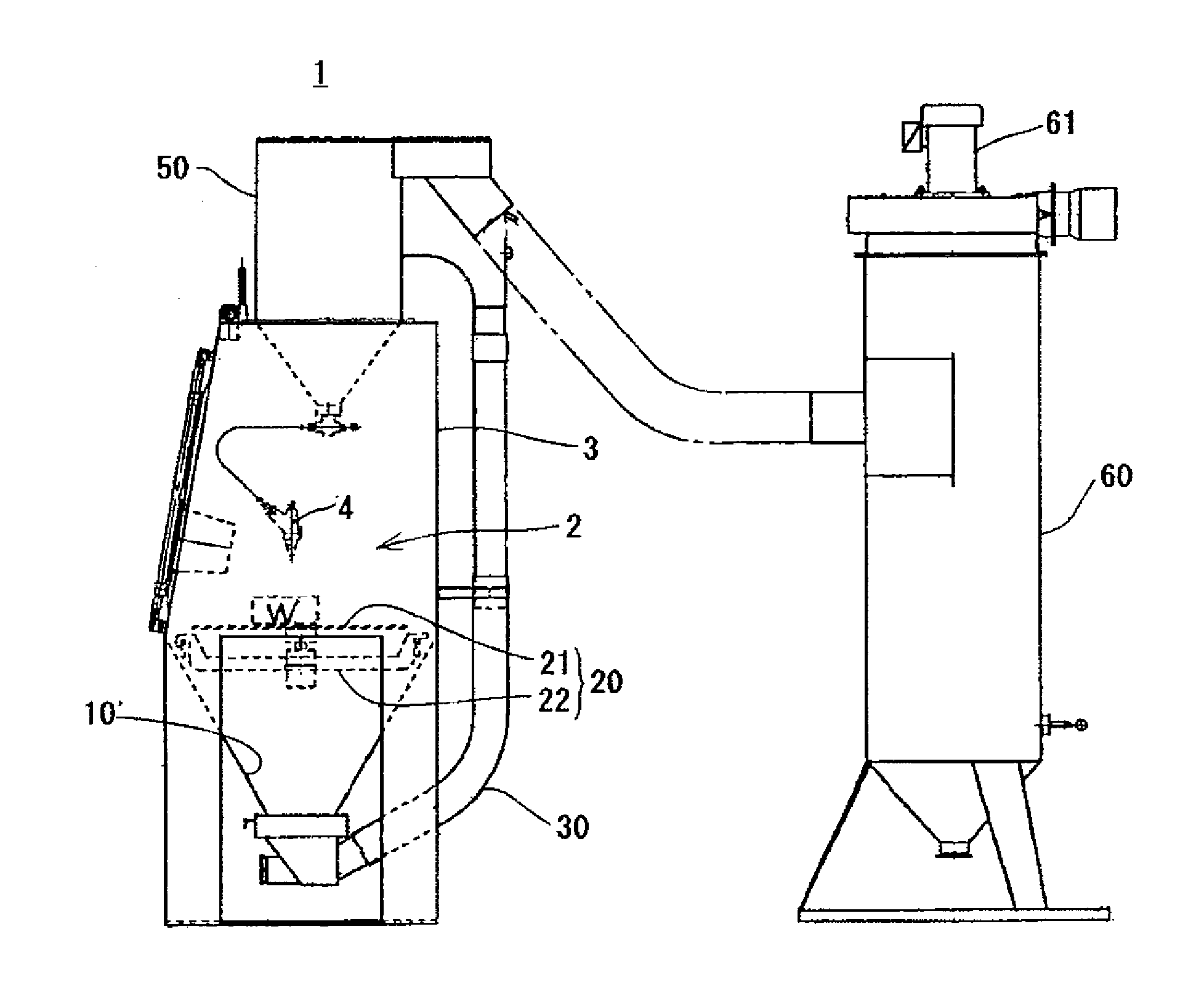
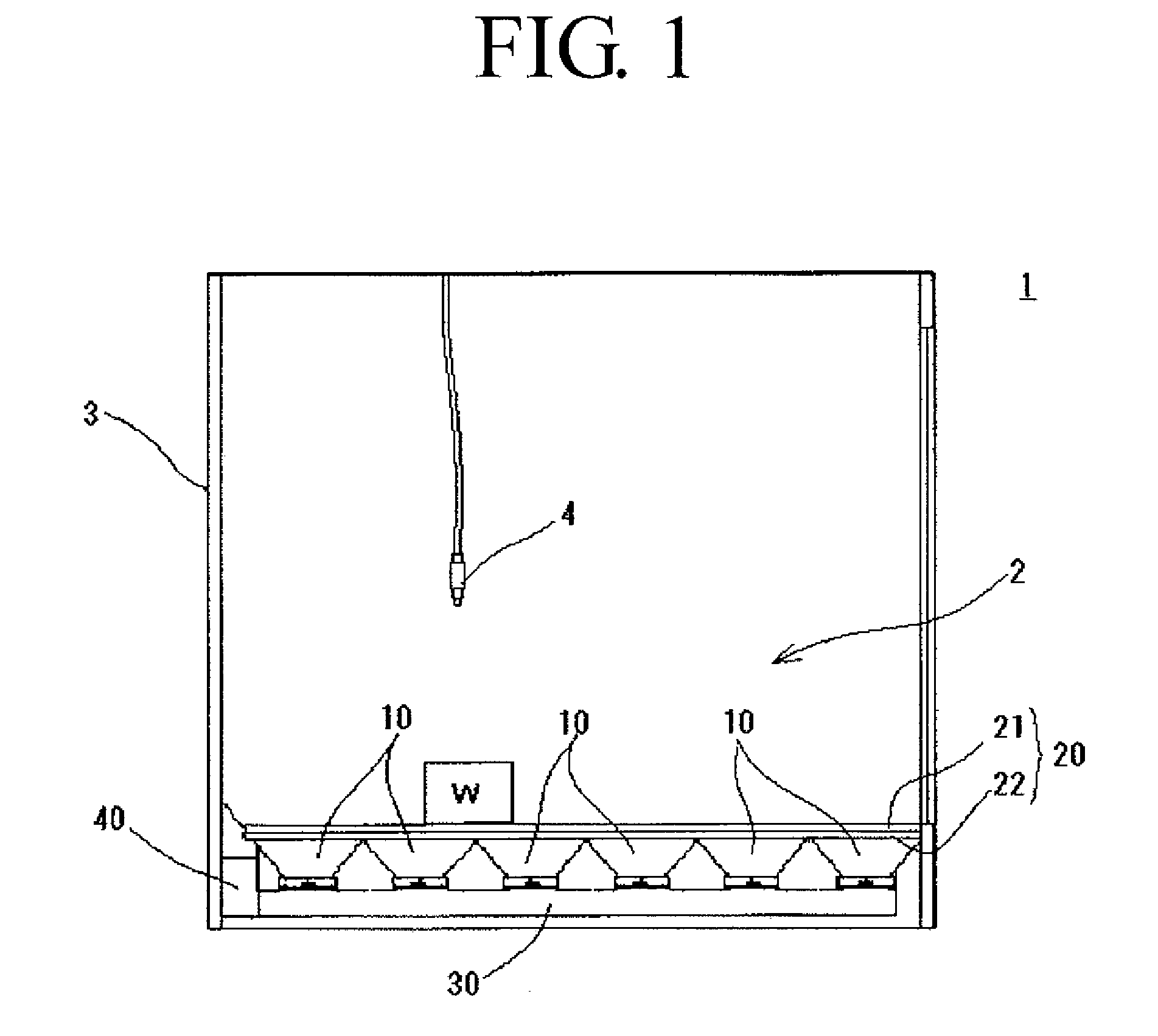
[0058]Referring to FIG. 1, reference numeral 1 denotes a blasting machine including an abrasive-recovery mechanism according to the present invention. This blasting machine 1 includes a cabinet 3 having a space in which a blasting chamber 2 is formed.

[0059]This cabinet 3 is shaped like a box having a space therein. An openable / closable door and a transport entrance covered with, for example, a flexible sheet are provided at a part of a wall surface of the cabinet 3 so that a workpiece W and an operator can enter the cabinet 3 through this transport entrance as required.

[0060]An abrasive-ejecting machine, such as an ejection nozzle 4, for ejecting the abrasive onto the workpiece W is housed in this cabinet 3. When the abrasive is ejected onto the workpiece ...


PUM


Abstract

A bottom wall surface of a blasting chamber of a blasting machine provided with hoppers for recovering an abrasive is formed at a lowest possible position. A cabinet 3 of a blasting machine 1 is compartmentalized at a predetermined position into an upper space and a lower space by mesh members (21, 22) that allow the abrasive to pass therethrough to form a blasting chamber 2 having a bottom wall surface 20 defined by the mesh members (21, 22). Hoppers 10 substantially shaped like an inverted quadrangular pyramid are disposed below the mesh members (21, 22) such that top portions of the hoppers 10 are opened toward the mesh members (21, 22) and that the bottom end of each of the hoppers 10 is made to communicate with suction means, such as a dust collector, through a recovery pipe 30.

Description

CROSS REFERENCE TO RELATED APPLICATION[0001]This application claims priority on JP 2007-266590, filed Oct. 12, 2007, hereby incorporated in its entirety by reference into this application.BACKGROUND OF THE INVENTION[0002]1. Field of the Invention[0003]The present invention relates to an abrasive-recovery mechanism in a blasting machine and, more particularly, to an abrasive-recovery mechanism for recovering an abrasive ejected mainly in a blasting chamber formed in a cabinet of a blasting machine.[0004]The blasting machine according to the present invention encompasses various types of blasting machines such as a sand-blasting machine for dry-ejecting or dry-projecting (hereinafter, referred to as “ejecting”, including projecting) a mixed fluid composed of a compressed gas, such as compressed air, and an abrasive; and a suction blasting machine or a direct-pressure blasting machine for use in a shot peening machine. The blasting machine according to the present invention also includ...

Claims


Application Information

Patent Timeline
Patent Type & Authority Applications(United States)
IPC IPC(8): B24C9/00
CPCB24C9/00
Inventor MASE, KEIJI
Owner FUJI MFG CO LTD
Why Eureka
Try Eureka