Programmable, digital vacuum-operated liquid sampler

a vacuum-operated, liquid sampler technology, applied in the direction of instruments, ac/dc measuring bridges, reference comparison, etc., can solve the problems of lack of repeatability, variance in sampling accuracy, and more scheduled maintenance, so as to prolong the life of the tubing and avoid deformation over time. , the effect of maximizing reliability

Active Publication Date: 2009-04-23
TELEDYNE INSTR INC
View PDF5 Cites 11 Cited by
  • Summary
  • Abstract
  • Description
  • Claims
  • Application Information

AI Technical Summary

Benefits of technology

[0011]The described pumping system is superior to peristaltic pumps because it moves the product without pinching the tubing that it goes through. Thus, it does not disturb or crush possible solids that may be suspended in the sample. It is also superior because the peristaltic system creates more wear on the intake tubing which can cause variances in sampling accuracy and requires scheduled maintenance more often. The discharge from the measuring chamber also leaves the tubing wide open as the sample passes through, leaving our system with a ⅜″ (ID) intake and outlet system throughout without restrictions which peristaltic pumps cannot offer. Our measuring system does not require any sensors for actually make contact with the product, instead digitally measuring the sample.
[0018]Another important object is to maximize reliability by extending tubing life. It is a feature of our invention that a vacuum system is employed, rather than a peristaltic pump, so the tubing through product movers is not degraded over time.

Problems solved by technology

The programmable device utilizes a highly reliable vacuum pressure pump rather than less-reliable, peristaltic pumping designs.
Vacuum lift technology has several intrinsic benefits over peristaltic pumps; however, it has traditionally also suffered from lack of repeatability.
It is also superior because the peristaltic system creates more wear on the intake tubing which can cause variances in sampling accuracy and requires scheduled maintenance more often.

Method used


Image

  • Programmable, digital vacuum-operated liquid sampler
  • Programmable, digital vacuum-operated liquid sampler
  • Programmable, digital vacuum-operated liquid sampler

Examples


Embodiment Construction

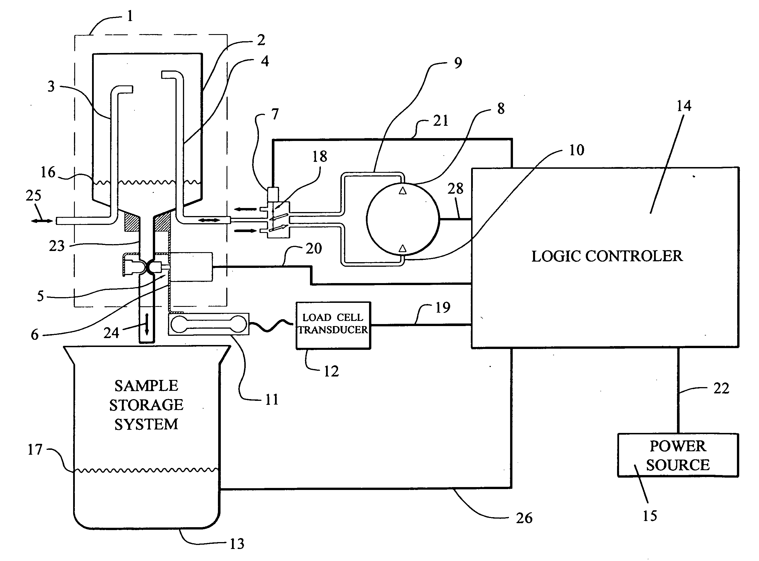
[0035]The instant liquid sampler repetitively suctions a liquid to be sampled, i.e., waste water, from a remote source. For example, samples may be obtained from a conventional sewage wet well buried in the earth. The automatic wastewater sampler combines a vacuum lift technique with real-time mass measurement and adaptive feedback logic to enable accurate, repeatable sampling heretofore unachievable with traditional vacuum lift techniques. This invention, therefore, has all of the advantages of vacuum lift while avoiding the traditional drawbacks.

[0036]Referring initially to FIG. 1, a sampling assembly 1 comprises a sampling chamber 2, a sampling intake port 3, an air port 4, a discharge port 23, a pinch valve 5, and a mechanical coupling 6 that contacts the load cell. The sampling chamber 2 in the first preferred embodiment illustrated in FIG. 1 comprises a plastic cylindrical housing which screws onto a cylindrical plastic base and joins with a water-tight seal.

[0037]The sampling...


PUM

PropertyMeasurementUnit
volt flow voltageaaaaaaaaaa
massaaaaaaaaaa

Abstract

A programmable liquid sampler for obtaining and digitally analyzing multiple, sequential samples in real time from an external source of liquid to be analyzed comprises an adaptive feedback algorithm for correcting sample weight measurements occasioned by vacuum delays. A sampling assembly receives and at least temporarily stores a sample drawn by suction through an air port that can also pressurize the chamber. A load cell determines sample mass through a logic controller that implements adaptive feedback by recognizing a desired target sample size, requesting an initial sample, and measuring the initial sample size. A variable scaling factor is derived by comparing the target sample size to said measured sample size and the subsequent requesting size is scaled. Samples can be stored in multiple compartments of a radial table that is indexed by the computer software for proper sample control.

Description

CROSS REFERENCE TO RELATED APPLICATION[0001]This application claims the filing date of, and is based upon, prior U.S. provisional Patent Application Ser. No. 60 / 835,510, filed Oct. 20, 2006, and entitled Programmable Digital Vacuum Operated Liquid Sampler.BACKGROUND OF THE INVENTION[0002]I. Field of the Invention[0003]The present invention relates generally to a bulk density sampling apparatus for continuously and repetitively measuring liquid samples from a bulk source and storing them for subsequent testing. More particularly, the present invention relates to a digitized, electronic liquid sampler that adaptively compensates and corrects for sampling errors.[0004]II. Description of the Prior Art[0005]Sampling devices have long been used under a variety of circumstances for collecting sample materials of both free flowing solids and fluids from various sources. For example, samples are routinely collected from waste water flow lines or reservoirs for subsequent testing and analysis...

Claims


Application Information

Patent Timeline
Patent Type & Authority Applications(United States)
IPC IPC(8): G01N1/14G01R35/00
CPCG01N1/14G01N33/18G01N2001/185G01N2001/1418G01N2001/1093
Inventor MILLER, JOHN KEVINSAGE, TONY RAYGILLIOM, ROBERT M.
Owner TELEDYNE INSTR INC
Why Eureka
Try Eureka