Method and apparatus for determining the frontal plane of the pelvic bone

a pelvic bone and frontal plane technology, applied in the field of pelvic inlet plane, can solve the problems of inability and inability to determine the pelvic inlet plane, and achieve the effect of determining the position relatively accurately

Active Publication Date: 2009-04-23
AESCULAP AG +1
View PDF15 Cites 12 Cited by
  • Summary
  • Abstract
  • Description
  • Claims
  • Application Information

AI Technical Summary

Benefits of technology

[0024]In both methods, it is possible, without knowledge of one of points A or B, to determine its position relatively accurately, and, therefore, the pelvic inlet plane can also be determined from the three points A, B and C without being able to directly determine the position data of one of points A and B.

Problems solved by technology

However, a precondition for this method is that the three prominent points be accessible, for example, during percutaneous palpation or when a preferably navigated ultrasonic sensor is used.
However, this is not possible in all cases, for example, when a patient is lying on his side on an operating table only one of the points A or B is accessible, i.e., either the left or the right spina iliaca anterior superior only.
It is, therefore, impossible to determine the pelvic inlet plane in this special position of the patient.

Method used


Image

  • Method and apparatus for determining the frontal plane of the pelvic bone
  • Method and apparatus for determining the frontal plane of the pelvic bone
  • Method and apparatus for determining the frontal plane of the pelvic bone

Examples


Embodiment Construction

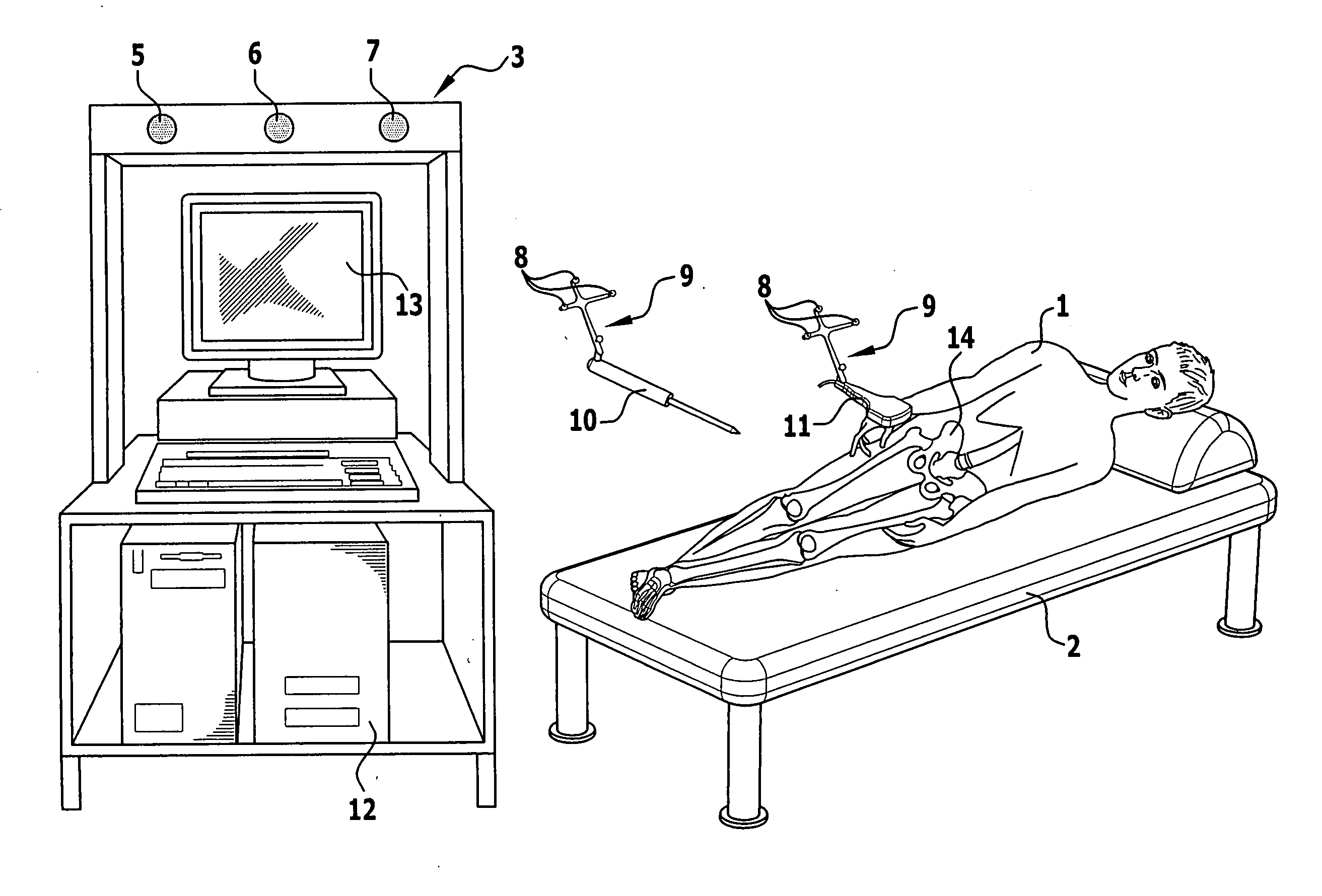
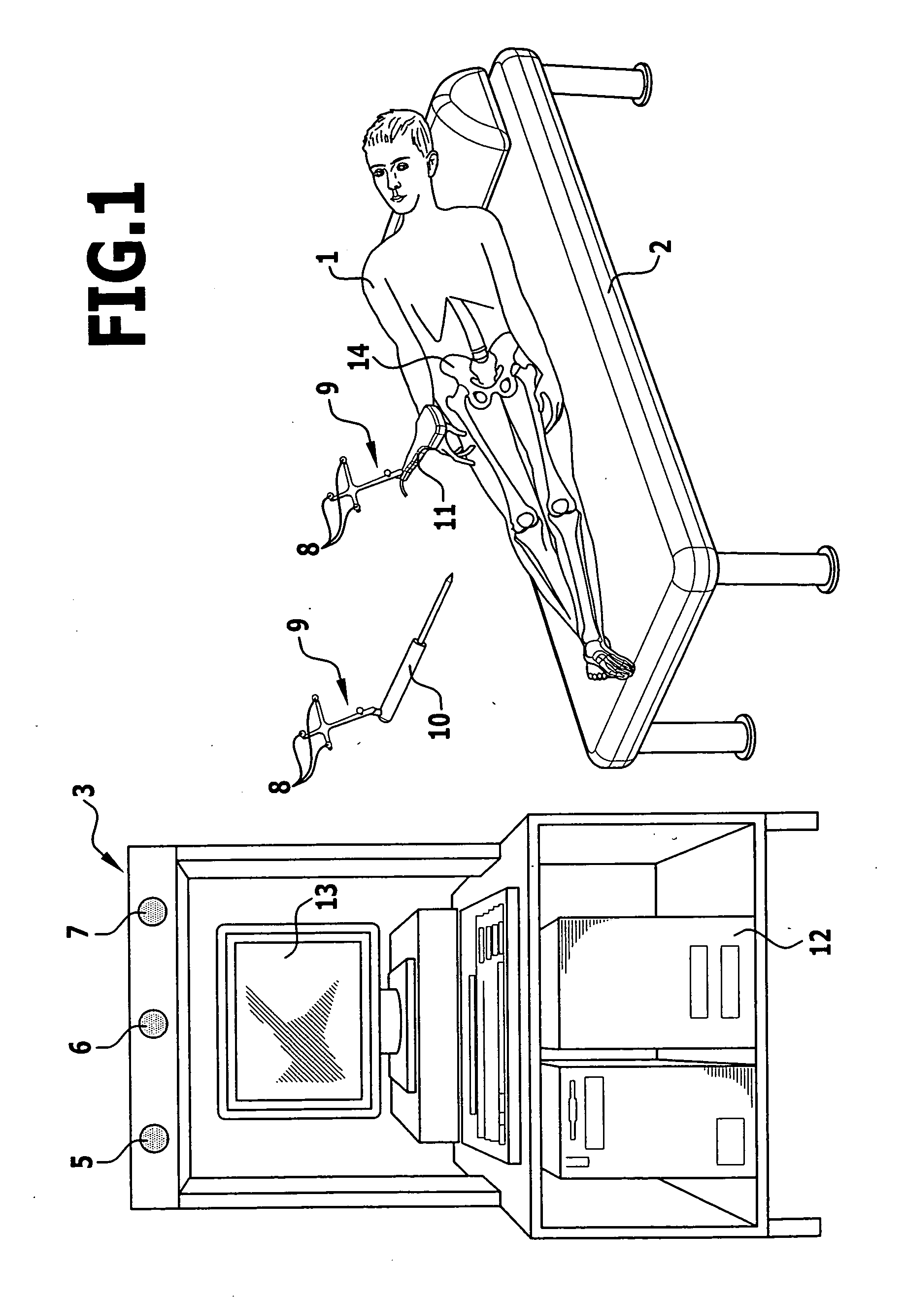
[0043]There is shown in FIG. 1 a patient 1 lying on his side on an operating table 2. Operations may be carried out on the patient in this position. Located beside the operating table 2 is a navigation system 3 with a number of radiation emitters 5, 6, 7, which at the same time are also configured as radiation receivers. The emitted radiation may be infrared radiation.

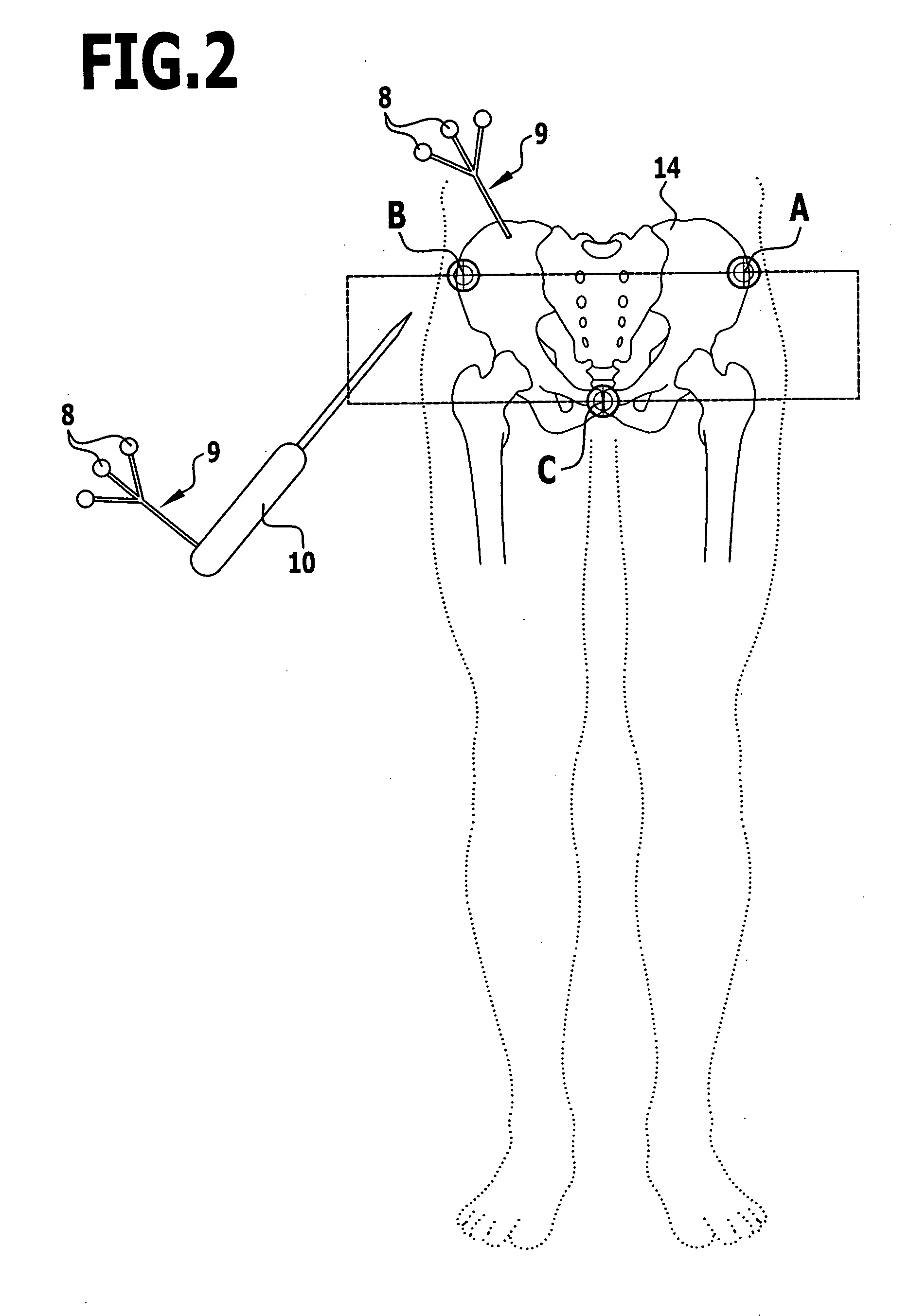
[0044]This radiation is reflected by reflective surfaces 8, which may be spheres arranged as markers 9 on various instruments 10, for example, a palpation instrument 10 and an ultrasonic sensor 11. The navigation system is thus able to detect in a manner known per se the position of the instruments in space, i.e., their exact position and their orientation.

[0045]A data processor 12 with a display device 13, in the form of a monitor in the embodiment shown, is also associated with the navigation system 3.

[0046]Three prominent points of the pelvic bone, which define a so-called pelvic inlet plane 15 (FIG. 2), are used to...


PUM


Abstract

In a method for determining the pelvic inlet plane of the pelvic bone, which is defined by the following three points of the pelvic bone:
point A: spina iliaca anterior superior left
point B: spina iliaca anterior superior right
point C: symphysis pubis,
by non-invasive determination of the position of one of the two points A or B and point C, in order to also be able to carry out this determination whenever point A or point B is not accessible, it is proposed that the position of the following points of the pelvic bone be additionally determined non-invasively:
point D: spina iliaca posterior superior left
point E: spina iliaca posterior superior right,
and that the position of the pelvic inlet plane be calculated from the position of the non-invasively determined points A or B, C, D and E.

Description

[0001]The present disclosure relates to the subject matter disclosed in German application number 10 2007 049 671.2 of Oct. 17, 2007, which is incorporated herein by reference in its entirety and for all purposes.BACKGROUND OF THE INVENTION[0002]The invention relates to a method for determining the pelvic inlet plane of the pelvic bone, which is defined by the following three points of the pelvic bone:point A: spina iliaca anterior superior leftpoint B: spina iliaca anterior superior rightpoint C: symphysis pubisby non-invasive determination of the position of one of the two points A or B and point C. The invention also relates to an apparatus for performing this method.[0003]When inserting implants and performing other operations, it is often necessary to describe the anatomical conditions in an abstract manner in order to record the anatomical conditions in mathematical models, for example, in connection with known navigation systems and with the processing of the thereby obtained...

Claims


Application Information

Patent Timeline
Patent Type & Authority Applications(United States)
IPC IPC(8): A61B19/00A61B8/00
CPCA61B5/103A61B5/4504A61B8/00G01S17/87A61B19/5244A61B2019/5268A61F2/4657A61B19/50A61B2034/2068A61B34/20A61B34/10
Inventor KOZAK, JOSEFKEPPLER, PETER
Owner AESCULAP AG
Why Eureka
Try Eureka