Articulated Joint with Adjustable Stiffness

Inactive Publication Date: 2009-04-23
FNS TECH APS
View PDF6 Cites 2 Cited by
  • Summary
  • Abstract
  • Description
  • Claims
  • Application Information

AI Technical Summary

Benefits of technology

[0021]The cylinder radial restriction means at the bottom of the cylinder serves to avoid that the float member falls out of the cylinder which could be the situation when a very dense layer of particulate material needs to be cooled in that the low air resistance through a thin particulate layer will create the situation where only a very limited amount of cooling air is needed. The radial restriction means at the top of the cylinder serves to limit the upward movement of the float member and at the same time create a gasket seat such that, as the float member engages the uppermost radial restriction means the air stream through the cylinder is discontinued.
[0024]By adjusting the weight of the float members or the cross sectional areas of the cylinders the apertures containing float members will close at different air pressure levels. This provides for a better adjustment, i.e. that the air flow control device will be able to regulate the air flow through the particulate bed, more precisely and in a better response to the thickness and the density of the particulate bed material such that an improved cooling / heat exchange will take place in relationship to the amount of ventilation air.
[0029]In order to provide further adjustment possibilities, the invention in a further advantageous embodiment may be provided with a hood, covering a substantial part of the front side of the base plate, where said hood is pivotably connected to the base plate, such that an adjustable gap is provided between the front side of the base plate and the rim of the hood. The hood and the pivotal mounting of the hood creates a ventilation gap between the hood and the base plate such that the hood and especially the adjustment of the gap will serve as an overriding air flow resistance component. The air flow control devices may be adjusted in use, such that an even distribution of the entire ventilation air led to the compartment under the particulate bed due to the provision of the hoods may have a coarse adjustment of the ventilation air across the entire cooling area. By furthermore adjusting the size of the apertures not having float members, each individual air flow control device may be adjusted in relation to a neighbouring float device such that the distribution of ventilation air is further improved and finally by adjusting the air flow through the float members and the weight of the float members a very precise adjustment of the entire air flow across the cooling bed of particulate material may be designed and adjusted whereby optimal cooling is achieved.

Problems solved by technology

In connection with the cooling of cement clinker which is discharged from the kiln installed ahead of the cooler it has, however, emerged that the clinker is not always uniformly distributed across the width of the cooler.
Such uneven distribution of the clinker will also entail that the cooling air in the areas where it encounters least resistance will simply cool the clinker more, due to the higher air flow through the clinker bed in the area.
The non expansion will result in a lower pressure drop when passing the clinker bed, which again will lead to even more cold air passing through specifically in this area.
The instability in the cooling process by having air, which is a compressive media, passing the clinker bed is apparently inevitable.
The result of this instability is also causing a reduced heat exchange effect.
But this resulted in a higher compartment pressure, due to the higher pressure difference across the orifices.
Hereby the fans supplying the air to the compartments will consume more electricity.
Nevertheless this results in instability of the operation of the whole cooler / kiln system, and therefore it is not realizable.
The devises would reduce the flow in this area, but with a constant flow from the fan, this would result in a higher pressure in the whole compartment, and hereby more air would pass the bed in the before mentioned area, the device would close even more, which would results in higher pressure in the compartment.
This is due to the fact that after a blow through of the fluid or spouted bed the device will close—but even with a small amount of air in the remaining opening, the fluid or spouted bed will still collapse.

Method used


Image

  • Articulated Joint with Adjustable Stiffness
  • Articulated Joint with Adjustable Stiffness
  • Articulated Joint with Adjustable Stiffness

Examples


Embodiment Construction

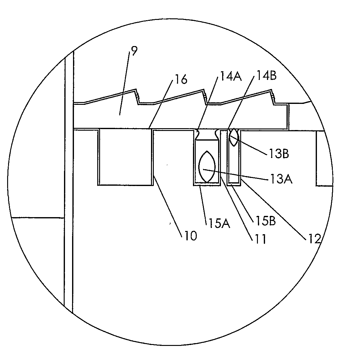
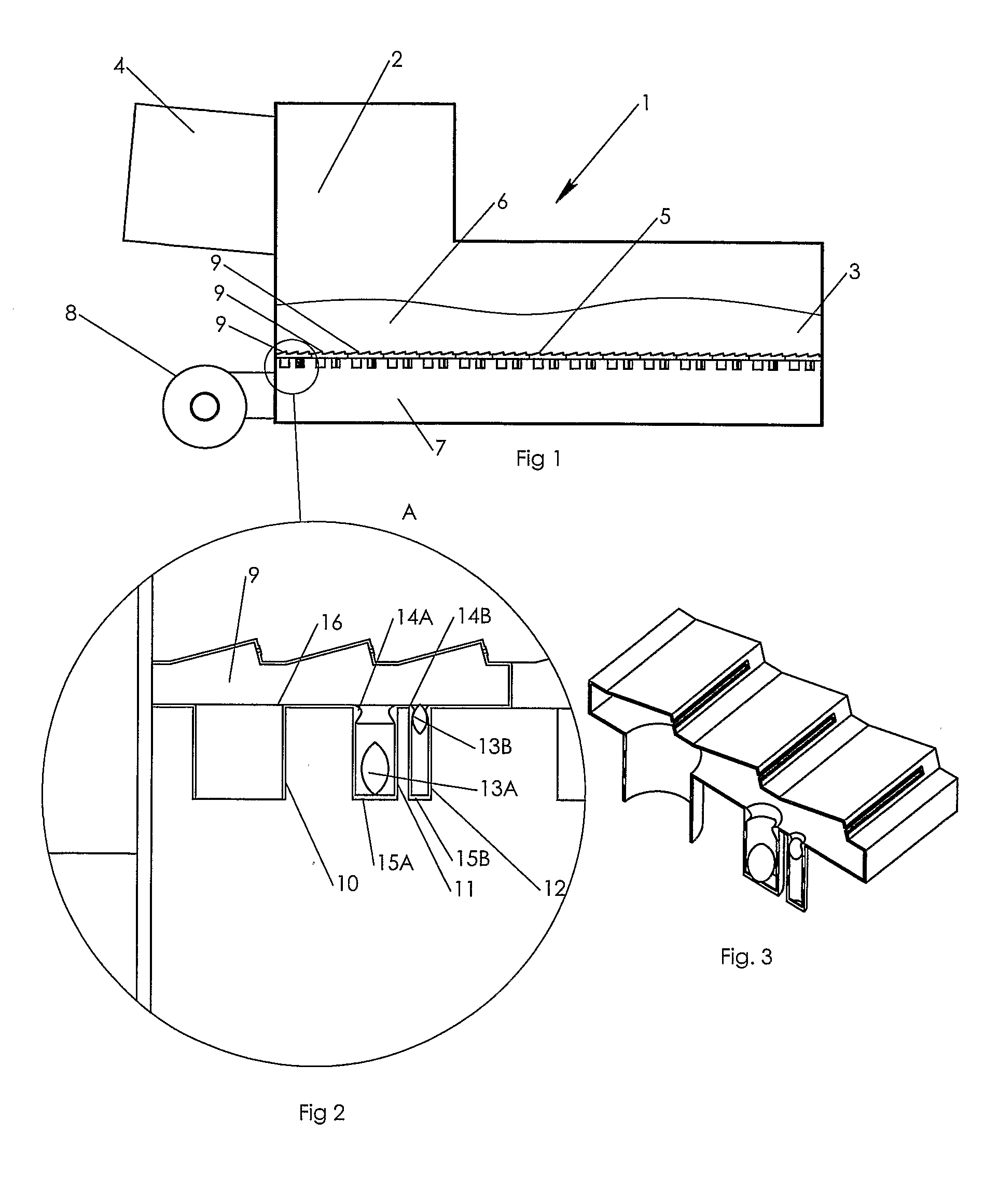
[0039]In FIG. 1 is shown a cooler 1 which comprises an inlet end 2 and an outlet end 3. The cooler is connected to a rotary kiln 4 from which it receives hot material which is to be cooled. The material from the rotary kiln drops onto a distribution bottom 5 provided in the cooler 1 and it is conveyed as a material layer 6 on the distribution bottom 5 from the inlet end 2 to the outlet end 3 of the cooler 1 by means of transport—not shown. The means of transport could, not limited to, be: reciprocating grates, reciprocating bars or a walking floor principle. Under the distribution bottom 5 the cooler 1 comprises of one or more compartments 7, where each is supplied with cooling air from a fan installation 8. The compartment 7 may both in the longitudinal direction of the cooler and transversely hereof, be divided into a number of smaller compartments, not shown, and, if so, cooling air is supplied to each single compartment. The distribution bottom 5 is sectionalised in a number of ...


PUM

PropertyMeasurementUnit
Lengthaaaaaaaaaa
Fractionaaaaaaaaaa
Fractionaaaaaaaaaa

Abstract

A bed of particulate material 6 is supported by an air distribution bottom 5. Under the distribution bottom 5 exist one or more compartments 7, which each being supplied with cooling air from a fan installation 8. The distribution bottom 5 is sectionalised in a number of smaller areas 9. Each smaller distribution area 9 is connected to the compartment 7 by ducts 10, 11 and 12. The one duct 10 does have a fixed orifice area. The ducts 11 and 12 do have floaters 13A / 13B end stop 14A / 14B and bottom support 15A / 15B. It is hereby obtained that the total pressure loss across the air distribution bottom can be reduced, and so that the flow of the treatment air through the material bed is distributed in a desirable manner across the entire air distribution bottom regardless of the composition of the material bed and the distribution thereon, and optimal heat exchange efficiency is obtained.

Description

FIELD OF THE INVENTION[0001]The present invention relates to a method for cooling a bed of particulate material which is supported by air which via ducts is conducted in sectionalised manner to and directed up through the air distribution bottom and the bed of material from one or several underlying compartments, while the particulate material is transported horizontally from the inlet end to the outlet end of the distribution bottom.[0002]The invention relates also to an air flow device for carrying out the method according to the invention.BACKGROUND OF THE INVENTION[0003]An example of a device which comprises of an air distribution bottom, is a cooler for cooling, for example cement clinker. In such a cooler the primary aim is to achieve a favourable degree of heat exchange between the clinker and the cooling air so that a substantial part of the thermal energy contained in the hot clinker can be returned to the kiln system in the cooling air, while, at the same time, the clinker...

Claims


Application Information

Patent Timeline
IPC IPC(8): F28C3/16F28F27/02F27D15/02
CPCC04B7/47F27B7/383F28F27/02F28C3/16F27D15/0213
Inventor FONS, MOGENS JUHL
Owner FNS TECH APS
Why Eureka
Try Eureka