Gas turbine oil scavenging system

a gas turbine and oil scavenging technology, applied in the direction of turbines, drip or splash lubrication, machines/engines, etc., can solve the problems of relative over-weight and overweight of displacement pumps and dedicated gear trains, and achieve the effect of low engine power

Active Publication Date: 2009-04-23
PRATT & WHITNEY CANADA CORP
View PDF12 Cites 35 Cited by
  • Summary
  • Abstract
  • Description
  • Claims
  • Application Information

AI Technical Summary

Benefits of technology

[0007]In a still further aspect, the present invention provides a method for ventilating an oil scavenging system in a gas turbine engine which comprises steps of directing a flow of exhaust air from an air / oil separator in the oil scavenging system to an air-air ejector; and supplying a bleed air flow from the gas turbine engine to the air-air ejector to drive the flow of exhaust air to pass through the air-air ejector to be vented into the atmosphere in order to de-pressurize the air / oil separator at a low level of engine power.

Problems solved by technology

Those displacement pumps and the dedicated gear train are relatively oversized and overweighted in the environment of a gas turbine engine, particularly when used for aircraft.

Method used


Image

  • Gas turbine oil scavenging system
  • Gas turbine oil scavenging system
  • Gas turbine oil scavenging system

Examples


Embodiment Construction

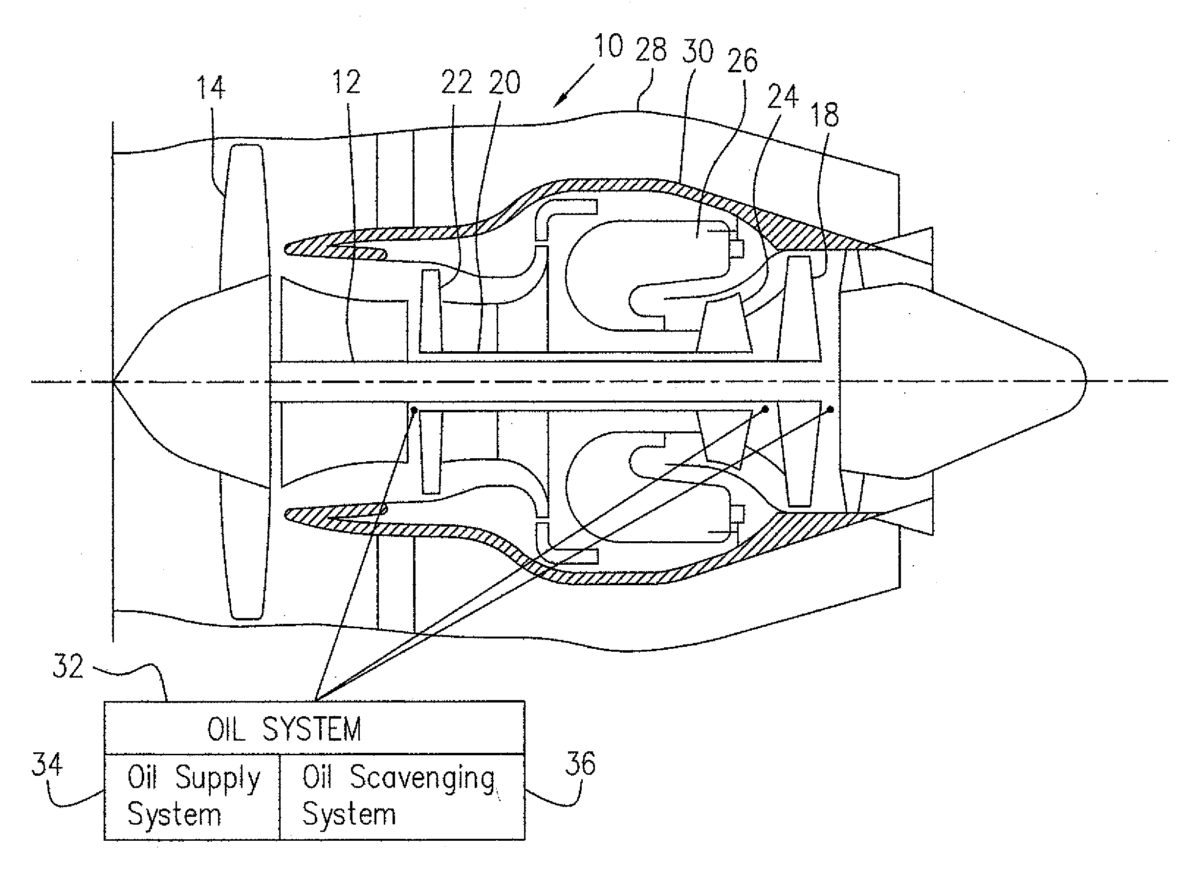
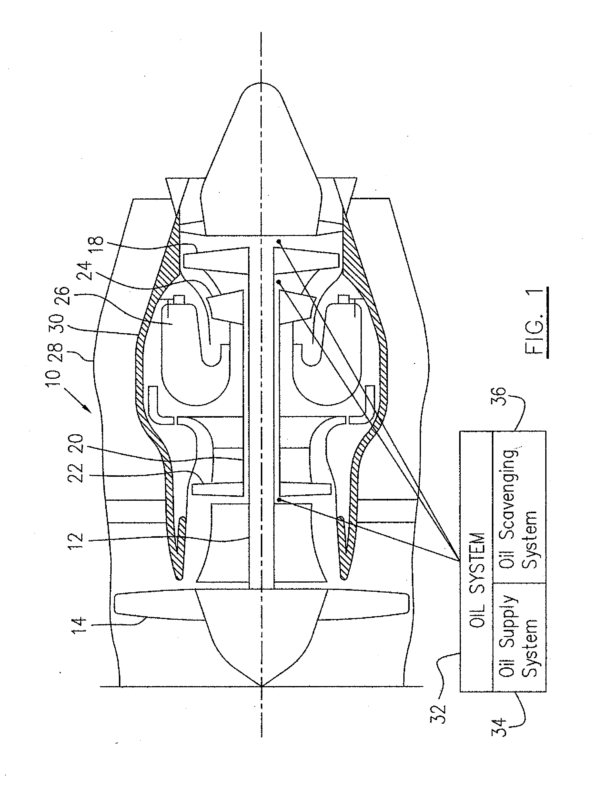
[0014]FIG. 1 illustrates an exemplary gas turbine engine 10 which includes an outer bypass duct 28, a gas generator case 30, a low pressure spool assembly seen generally at 12 which includes a fan assembly 14 and a low pressure turbine assembly 18, and a high pressure spool assembly seen generally at 20 which includes a high pressure compressor assembly 22 and a high pressure turbine assembly 24. The gas generator case 30 surrounds the low and high pressure spool assemblies 12 and 20 in order to define a main fluid path (not indicated) therethrough, which includes a combustor 26.

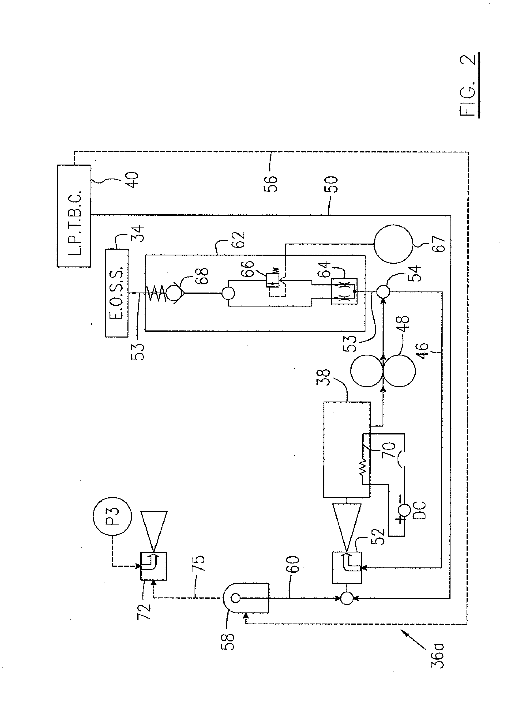
[0015]Referring to FIGS. 1-4, the gas turbine engine 10 includes an oil system 32 for circulating cooling and lubricant oil within the engine. The oil system 32 includes an engine oil supply system (E.O.S.S.) 34 for delivering oil from a source such as an oil tank 38 to various locations in the engine, for example, to a low pressure turbine bearing cavity (L.P.T.B.C.) 40, a high pressure turbine bearing cavi...


PUM


Abstract

A method for scavenging oil in a gas turbine engine comprises using a driving fluid flow to drive a flow of a fluid collected in an oil system of the engine to pass through an ejector and then the driven flow of the fluid is directed to be discharged into an oil tank.

Description

TECHNICAL FIELD[0001]The invention relates generally to gas turbine engines and, more particularly, to an improved gas turbine oil scavenging system.BACKGROUND OF THE ART[0002]Gas turbine engines have oil systems to meet the needs of rotating components of the engines for continuous oil flows for cooling and lubricating those rotating components. An oil system in a gas turbine engine conventionally includes an oil supply system for delivering oil from an oil source such as an oil tank, to various locations within the gas turbine engine, and an oil scavenging system for recovering used oil from the various locations in the engine and discharging the recovered used oil back into the source such as the oil tank. In a conventional scavenging oil system, conventional displacement pumps which are driven by a dedicated gear train, are used as scavenging pumps. Those displacement pumps and the dedicated gear train are relatively oversized and overweighted in the environment of a gas turbine...

Claims


Application Information

Patent Timeline
Patent Type & Authority Applications(United States)
IPC IPC(8): F01M9/06
CPCF01D25/18F01M1/16F01M5/001F02C7/06F05D2260/601F16N2210/02F16N2270/60Y02T50/671F05D2260/602F16N39/04Y02T50/60
Inventor ALECU, DANIEL T.
Owner PRATT & WHITNEY CANADA CORP
Why Eureka
Try Eureka