Suction roller system

a roller system and suction bore technology, applied in the direction of instruments, printers, roads, etc., can solve the problems of insufficient ventilation, inconvenient installation, and insufficient suction, so as to reduce friction, reduce noise, and reduce the effect of space-saving installation

Inactive Publication Date: 2009-04-23
WINKLER DUNNEBIER GMBH
View PDF8 Cites 4 Cited by
  • Summary
  • Abstract
  • Description
  • Claims
  • Application Information

AI Technical Summary

Benefits of technology

[0010]To avoid a steep-flank partial vacuum surge that might occur, and the resulting loud bang that is caused by sudden ventilation of the ventilation channels by the opening situated in the closure plate, the opening is designed to have a width that narrows counter to the direction of rotation of the roller. A teardrop-shaped opening, in particular, leads to a significant reduction in the noise level.
[0011]In order to allow simple and space-saving installation of the closure plate, the closure plate is fixed in place on the housing of the suction roller system by means of pins. In an advantageous embodiment, in this connection, the face side that borders on the closure plate has a number of magnets. By way of these magnets on the face side of the suction roller, and the vacuum in the suction channels, the closure plate is held on the face side without any additional atmospheric air being able to penetrate between the closure plate and the face side of the suction roller. At the same time, however, rotation of the suction roller is not impaired by the connection with the closure plate fixed in place on the housing. To reduce the friction, the contact surfaces can be provided with friction-reducing coatings.
[0012]In an alternative, advantageous embodiment,

Problems solved by technology

In this connection, it can happen that the suction bores in the roller surface that are situated close to the opposite face side of the suction roller, which is usually closed, are not ventilated in timely manner, or ventilated only insufficiently by the control head.
Thi

Method used


Image

  • Suction roller system
  • Suction roller system
  • Suction roller system

Examples


Embodiment Construction

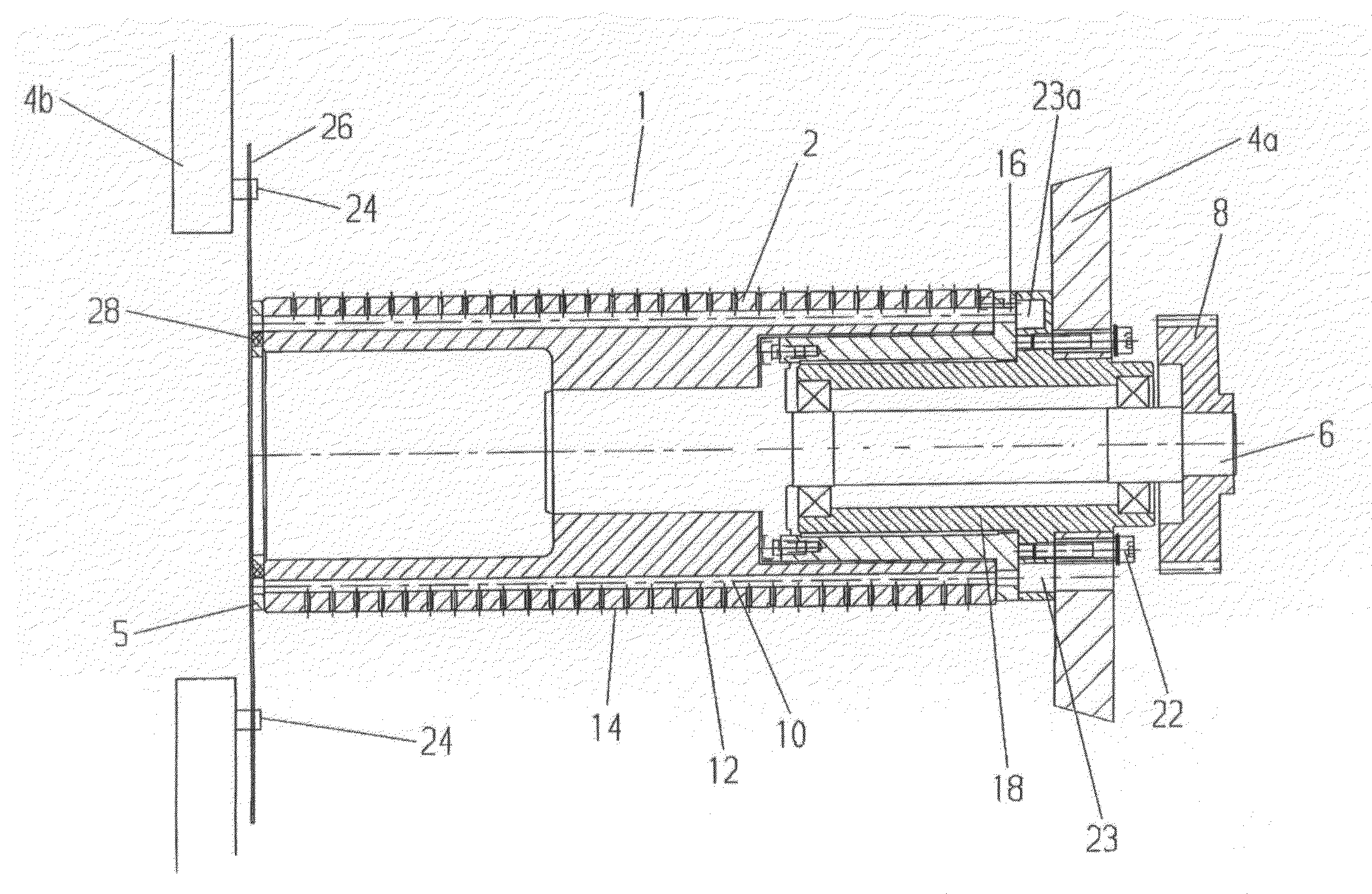
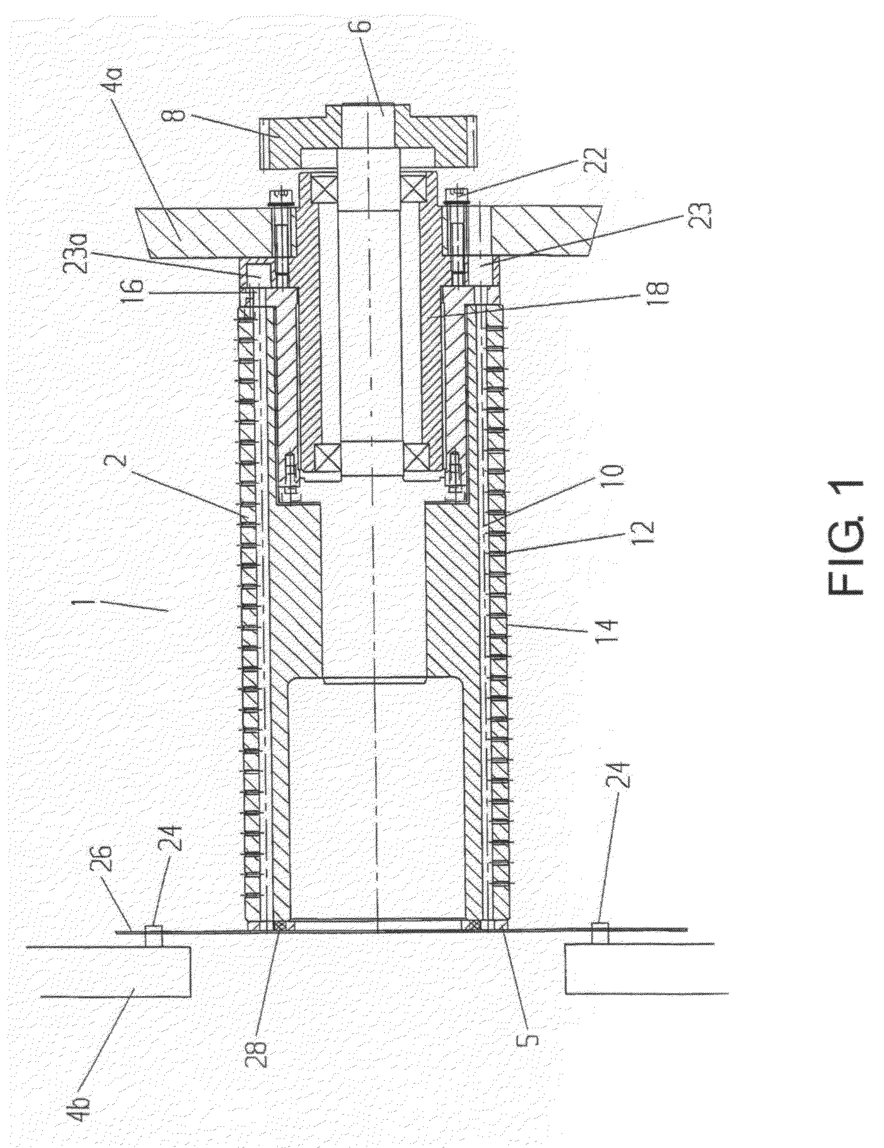
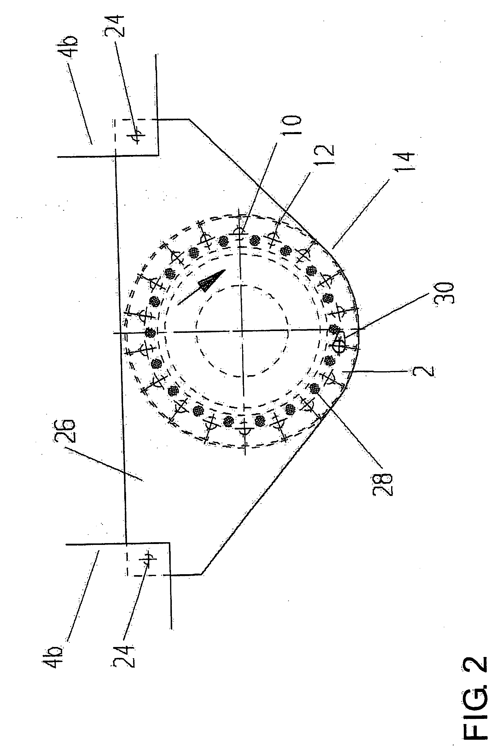
[0020]Referring now in detail to the drawings, in the exemplary embodiment of a suction roller system 1 shown in FIG. 1, a suction roller 2 is mounted in a machine frame 4a, using a shaft 6, so as to rotate freely, and is driven using a gear wheel 8. The suction roller has at least one suction channel 10, e.g. in the form of a longitudinal bore, from which suction bores 12 extend towards the surface 14 of suction roller 2, in the number and shape required, in each instance. Each suction channel 10 ends in a suction opening 16 at the end on the control head side. This suction opening 16 lies in a face surface of the suction roller 2.

[0021]With its face surface, suction roller 2 lies against a control head 18, which also has a face surface on the suction roller side, sliding on it or without contact, and in essentially airtight manner. Control head 18 is disposed in stationary manner and does not rotate. Fixation of control head 18 takes place by means of the screws 22.

[0022]Because t...


PUM

PropertyMeasurementUnit
Widthaaaaaaaaaa

Abstract

A suction roller system includes a suction roller and a control head having a ventilation zone situated at a face side of the suction roller. The suction roller system allows rapid ventilation of the suction bores situated on the face side opposite the control head via a cost-advantageous and space-saving expansion. For this purpose, the suction roller is equipped, on the second face side, with a closure plate having an opening that corresponds to the ventilation zone.

Description

BACKGROUND OF THE INVENTION[0001]1. Field of the Invention[0002]The present invention relates to a suction roller system including a suction roller and a control head having a ventilation zone situated at a face side of the suction roller.[0003]2. The Prior Art[0004]A control head for controlling the suction stretch of a suction roller is known from the German patent DE 2 943 562 C2 and from the reference DE 10 2005 062 348 A1; the suction roller is mounted so as to rotate and rests, with one face side, against a face side of the control head having at least one control channel. The suction roller has at least one longitudinal channel that ends on the face side and extends coaxially to supply suction bores that extend crosswise to the roller surface with at least a partial vacuum.[0005]In fast-running operation, the partial vacuum must be produced, and also canceled out again, very rapidly over the entire width of the suction roller, in each instance. In this connection, it can happ...

Claims


Application Information

Patent Timeline
IPC IPC(8): B65H20/12B65H27/00
CPCB65H5/226F16C13/00B65H2601/521B65H2406/3612Y10S493/917
Inventor RAUEISER, REINHARD
Owner WINKLER DUNNEBIER GMBH
Why Eureka
Try Eureka