
Apparatus and method for simultaneously acquiring multiple images with a given camera

Inactive Publication Date: 2009-04-23
VISION TECH INC
View PDF34 Cites 10 Cited by
  • Summary
  • Abstract
  • Description
  • Claims
  • Application Information

AI Technical Summary

Benefits of technology

[0022]It is another object that the apparatus is easily attachable to a given camera.
[0024]The first major component of the apparatus consists of a configuration of multiple mirrors attached at, and extending in front of, the entrance pupil of a conventional camera. The mirror system reduces the field of view of the apparatus from being the entire physical space in front of the camera to a part of it. This part is viewed directly by the camera. In addition, multiple images of this part are also formed by the mirror configuration, each being the cumulative result of reflections from one or more of the mirrors. The arrangement of the mirrors determines the size and shape of the directly viewed part of the space imaged, as well as the number of its images formed. Each such image acts as a separate virtual field of view, in addition to the directly viewed part of the field of view. The directly viewed part of field of view is imaged on a portion of the image sensor (array of light sensing elements) inside the camera. Each virtually viewed part of the field of view is imaged on a different portion of the sensor. The sensor is thus partitioned into multiple portions, each of which contains an image of the same, selected part of the field of view. The pixel locations where a specific scene point appears in all images are known because the same (real or virtual) field of view is captured in each image by a known mirror configuration.

Problems solved by technology

A conventional digital camera sensor captures only 8-bits (256 levels) of brightness information, called its dynamic range, which is typically inadequate and results in an image with many areas which are either too dark (under saturated or clipped) or too bright (oversaturated).
Furthermore, the number of beam splitters required may be too bulky to fit in the available space between the lens and the sensor.
Both of these features increase design size and complexity.
This requires a complex sensor.
Further, the need for multiple subpixels increases the overall pixel area, thus increasing pixel size and reducing pixel resolution achieved in comparison with a conventional sensor.
However, the need for computation translates into need for pixel area and therefore lower resolution.
Further, the time taken by the darkest regions to saturate increases the worst case image acquisition time, thus increasing sensitivity (e.g., blur) due to scene motion.
As Table 1 shows, one drawback of the prior art is that it fails to provide an apparatus or method for acquiring images consistent with objectives (i-v).

Method used


Image

  • Apparatus and method for simultaneously acquiring multiple images with a given camera
  • Apparatus and method for simultaneously acquiring multiple images with a given camera
  • Apparatus and method for simultaneously acquiring multiple images with a given camera

Examples


Embodiment Construction

[0030]For the purposes of promoting an understanding of the principles of the invention, reference will now be made to certain embodiments thereof and specific language will be used to describe the same. It will nevertheless be understood that no limitation of the scope of the invention is thereby intended, such alterations, further modifications and further applications of the principles of the invention as described herein being contemplated as would normally occur to one skilled in the art to which the invention relates.

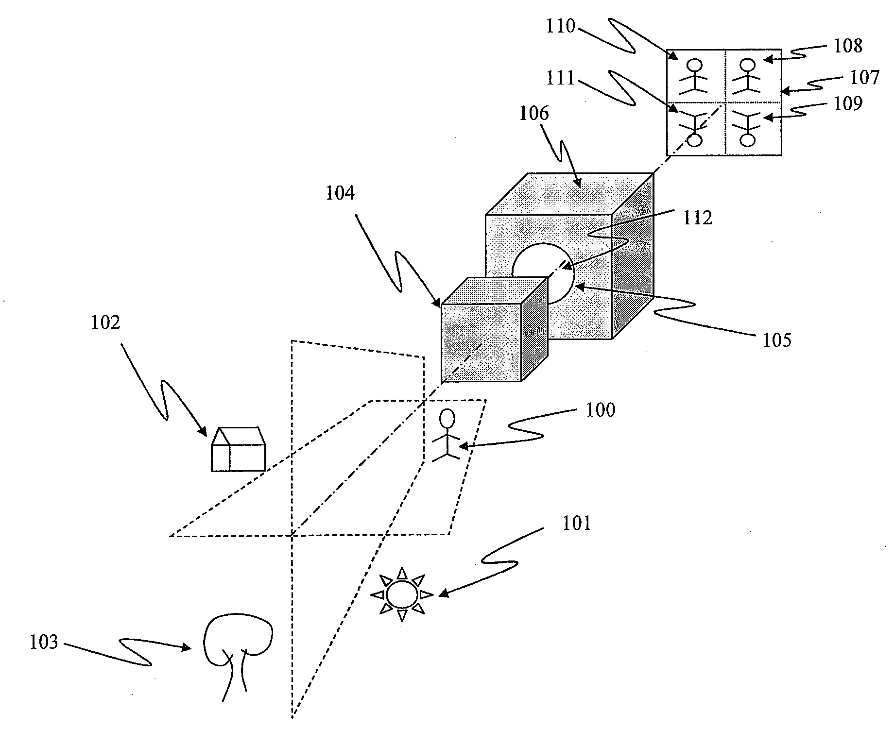
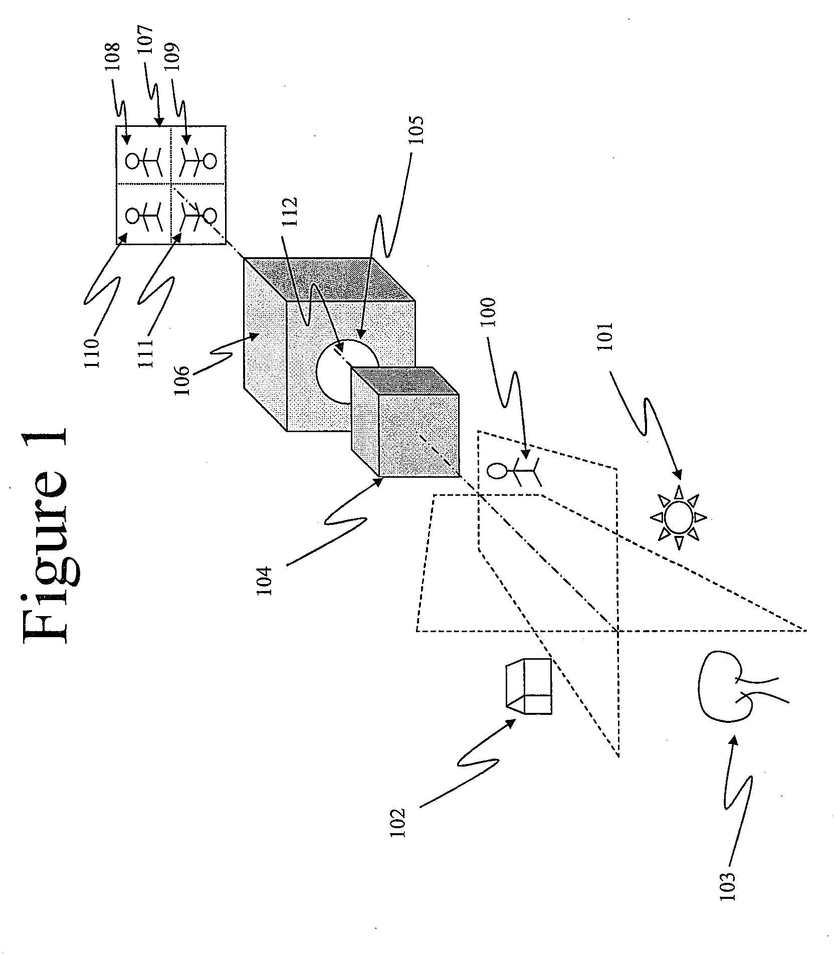
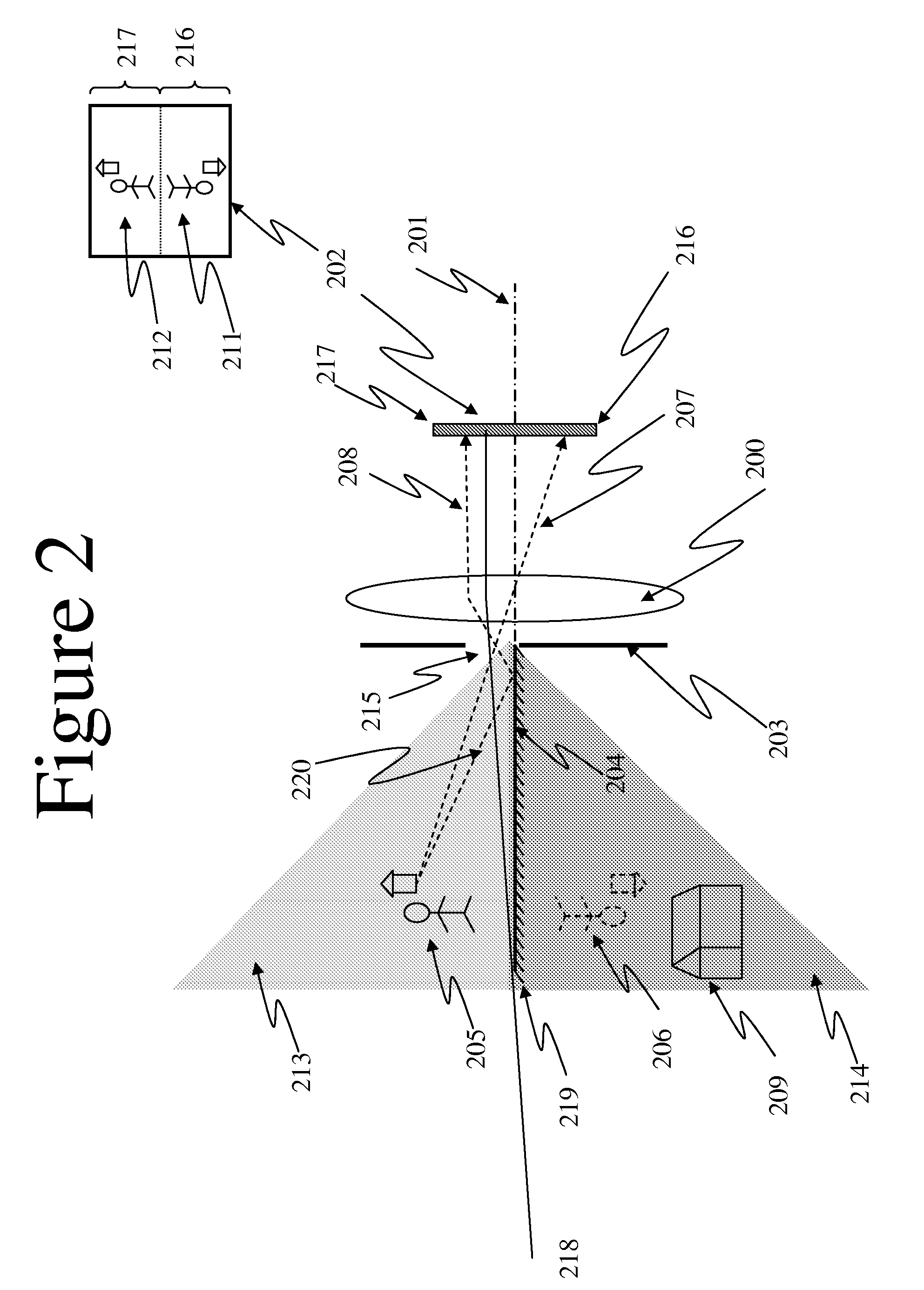
[0031]One embodiment of the invention is a box containing mirrors that attaches to the front of a given camera at its entrance pupil and extends in front of the camera. Only a part of the complete field of view of the camera is imaged by the invention. Multiple images of this part are formed in different portions of the same, single sensor. The properties of the mirrors are chosen according to the desired properties of the multiple images formed.

[0032]As shown in ...


PUM


Abstract

An apparatus and method for acquiring multiple images of a given scene. The apparatus allows a standard video imaging camera to simultaneously detect multiple images through the use of reflective surfaces. In at least one embodiment, the multiple images allow for a single image to be created having a high dynamic range. In another embodiment, method for efficiently determining an infrared image is provided.

Description

[0001]This application claims the benefit of U.S. Provisional Application No. 60 / 980,889, filed on Oct. 18, 2007, which is incorporated herein by reference in its entirety.TECHNICAL FIELD OF INVENTION[0002]The present invention relates to an imaging apparatus and, more particularly, to an apparatus and method for acquiring multiple images of a field of view, all from a single viewpoint but using different imaging parameters and captured in different parts of a given image sensor at a standard video rate.BACKGROUND OF THE INVENTION[0003]A camera capable of acquiring multiple types of images of the same field of view (the extent of the scene captured in the image by the camera) is highly desirable in many applications such as surveillance, scene modeling and inspection. As used herein, the phrase “multiple types of images” is intended to mean the use of different imaging parameters such as the degree of exposure used and the wavelengths captured, just to name two non-limiting examples...

Claims


Application Information

Patent Timeline
IPC IPC(8): H04N5/228H04N5/225
CPCG03B19/00H04N3/1593H04N13/0217H04N5/355H04N5/2355H04N13/218H04N23/741H04N25/41H04N25/57
Inventor AHUJA, NARENDRAAGGARWAL, MANOJ
Owner VISION TECH INC
Learn More