Liquid crystal display panel

a display panel and liquid crystal technology, applied in static indicating devices, instruments, non-linear optics, etc., can solve the problems of easy horizontal crosstalk, many defects in display quality, and easy crosstalk, so as to reduce the differences increase the consistency of rc delay for individual scanning lines, and reduce power consumption

Active Publication Date: 2009-04-23
KUSN INFOVISION OPTOELECTRONICS
View PDF5 Cites 14 Cited by
  • Summary
  • Abstract
  • Description
  • Claims
  • Application Information

AI Technical Summary

Benefits of technology

[0014]An LCD panel in accordance with an embodiment of the invention not only can be applicable to Dot Inversion Driving with low power consumption implemented by changing common voltage, but also has the consistency of the RC delay for individual scanning lines increased, and thereby the differences of RC delay for individual scanning lines are reduced, the uniformity of the display frame on the LCD panel is ensured and the display quality of the LCD is improved.
[0015]The method for increasing wiring capacitance on a scanning line in a LCD panel in accordance with an embodiment of the invention can be applied in those LCD panels having the problem of the RC delay for individual scanning lines being inconsistent, so as to increase the consistency of the RC delay for individual scanning lines and thereby achieve uniformity of the display frame on the LCD panel.

Problems solved by technology

However, the light transmittance of the liquid crystal layer cannot remain constant between continuous frames, and thereby causing flickers.
Further, in such driving technique, crosstalk easily occurs due to interference between adjacent data.
However, since the voltage with a same polarity is applied to those pixels arranged horizontally, horizontal crosstalk easily occurs.
As can be seen, Frame Inversion Driving and Row Inversion Driving cause many defects in display quality.
As a result, there are large differences between the driving conditions of the pixel units connected to the scanning lines G0 and GN and the pixel units connected to other scanning lines, thereby causing non-uniformity of luminance and color.

Method used


Image

  • Liquid crystal display panel
  • Liquid crystal display panel
  • Liquid crystal display panel

Examples


Embodiment Construction

[0032]Some illustrative embodiments of the invention will be described as follows with reference to the accompany drawings.

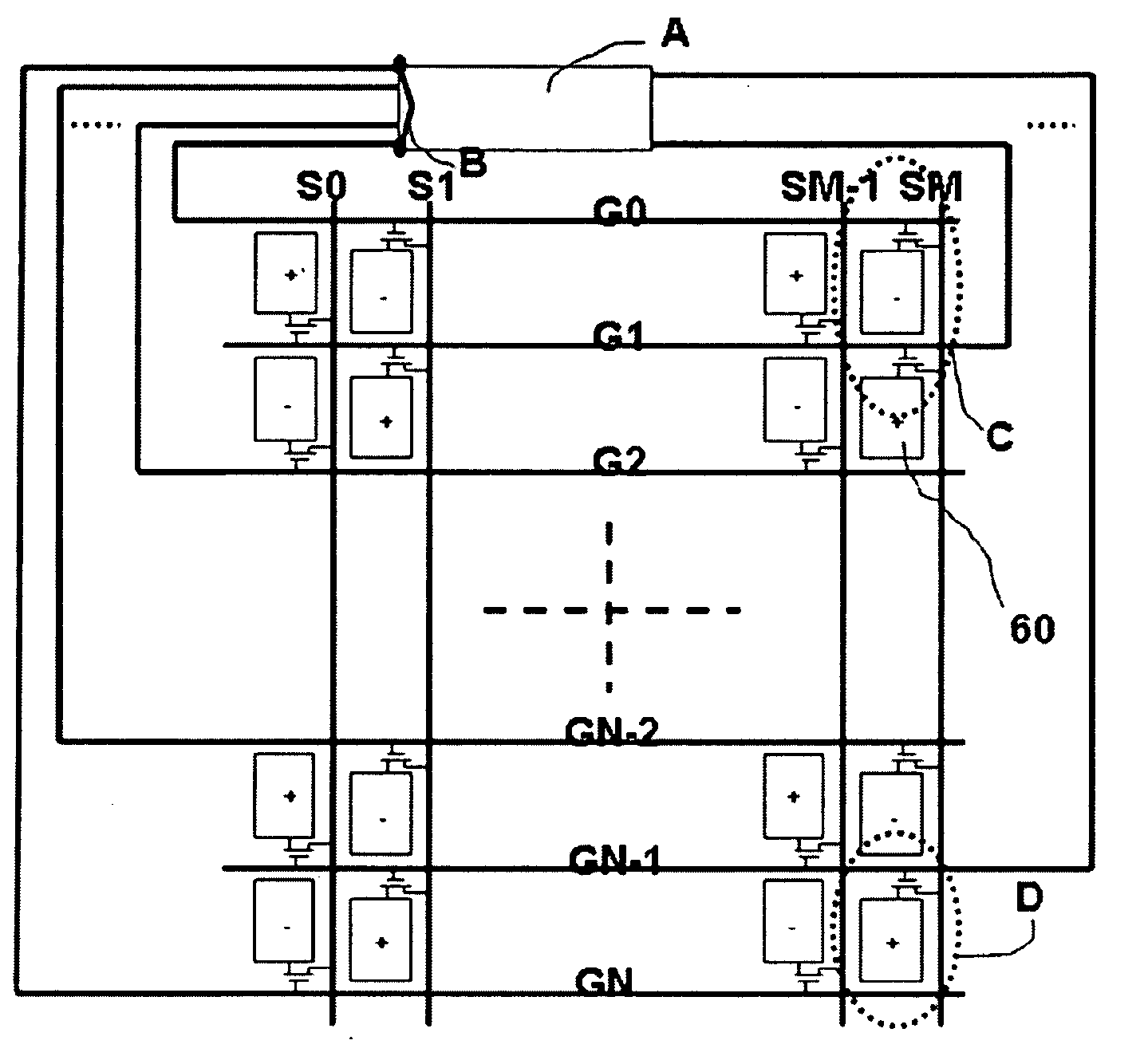
[0033]FIG. 5(a) is a simplified schematic diagram of a LCD panel according to an embodiment of the invention (for clarity only an array substrate is shown; a color filter substrate and a liquid crystal layer in the panel are omitted). Similar to the LCD panel shown in FIG. 4, in the LCD panel of the embodiment, A represents an IC PAD, and B represents a connecting line that connects the pins for the scanning lines G0 and GN. Scanning signals are simultaneously applied to the scanning lines G0 and GN whose pins are connected when the scanning signals are sent out, and thus data signals can be simultaneously supplied via data lines to both the pixel units in the even-numbered columns being connected to G0 and the pixel units in the odd-numbered columns being connected to GN. The LCD panel according to the embodiment comprises a number of scanning lines G0-GN, a nu...


PUM

PropertyMeasurementUnit
sizeaaaaaaaaaa
conductiveaaaaaaaaaa
driving polaritiesaaaaaaaaaa

Abstract

The invention discloses a liquid crystal display panel, comprising pixel electrodes, common electrode lines, data lines and scanning lines, wherein at least two of the scanning lines are electrically connected to each other. The liquid crystal display panel has a plurality of conductive sections are disposed above at least part of each of the scanning lines other than said at least two scanning lines and electrically connected to the common electrode lines. The liquid crystal display panel of the invention can use Dot Inversion Driving with low power consumption. Meanwhile, the invention improves consistency of the RC delays on the individual scanning lines, decreases the difference among the RC delays of scanning signals on all of the scanning lines, and thereby achieves uniformity of a display frame on the liquid crystal display panel.

Description

TECHNICAL FIELD[0001]The present invention relates to a liquid crystal display panel and a liquid crystal display apparatus, and in particular, to a liquid crystal display panel having low driving power consumption and a uniform display frame.BACKGROUND[0002]Liquid crystal displays (LCDs) are advantageous in being light, thin, having low power consumption and emitting no radiation, thereby gradually superseding traditional Cathode-Ray Tube (CRT) displays. Today, LCDs have been widely used in electronic products such as high image quality digital televisions, desktop computers, personal digital assistants (PDAs), notebook computers, digital cameras, mobile phones, and the like.[0003]Because liquid crystal molecules may be electrically decomposed when being subjected to an offset voltage for a long time, LCDs typically employ an Alternating Current (AC) driving technique, i.e. data signals are alternated between positive and negative polarities. If a voltage of a pixel electrode is hi...

Claims


Application Information

Patent Timeline
Patent Type & Authority Applications(United States)
IPC IPC(8): G02F1/1333G02F1/1343G09G3/36
CPCG09G3/3614G09G2320/0223G09G2300/0426G09G3/3648
Inventor CHUNG, TE-CHENJEN, TEAN-SEN
Owner KUSN INFOVISION OPTOELECTRONICS
Why Eureka
Try Eureka