Inverter, more specifically for photovoltaic plants

a photovoltaic plant and inverter technology, applied in the field of inverters, can solve the problems of high loss when compared to mosfets, dangerous touch voltages on the glass surface of solar panels, etc., and achieve the effect of preventing high frequency interference and capacitive leakage currents and high efficiency

Active Publication Date: 2009-04-23
SMA SOLAR TECH AG
View PDF6 Cites 16 Cited by
  • Summary
  • Abstract
  • Description
  • Claims
  • Application Information

AI Technical Summary

Benefits of technology

[0011]It is the object of the invention to provide for a high efficiency transformerless inverter while preventing high frequency interferences and capacitive leakage currents from occurring on the generator side.

Problems solved by technology

Capacitive leakage currents occur hereby at the solar generator, which can on the one side damage the solar cells and on the other side cause hazardous touch voltages to occur at the glass surface of solar panels.
For this reason, it makes sense to use for the upper switches of the bridge IGBTs for example, which are connected together with additional anti-parallel discrete diodes but suffer from the disadvantage of higher losses when compared to the MOSFETs.

Method used


Image

  • Inverter, more specifically for photovoltaic plants
  • Inverter, more specifically for photovoltaic plants
  • Inverter, more specifically for photovoltaic plants

Examples


Embodiment Construction

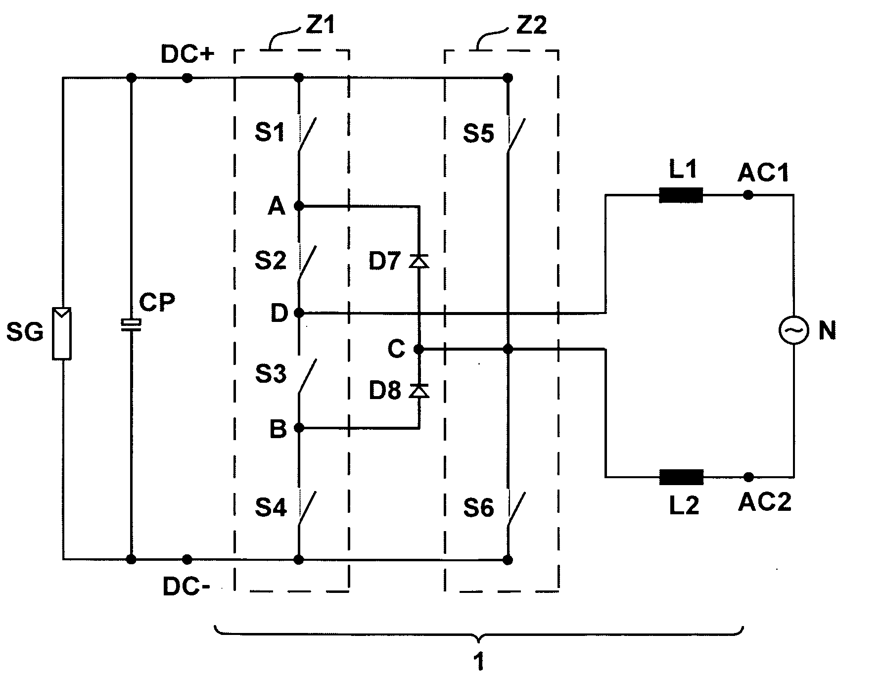
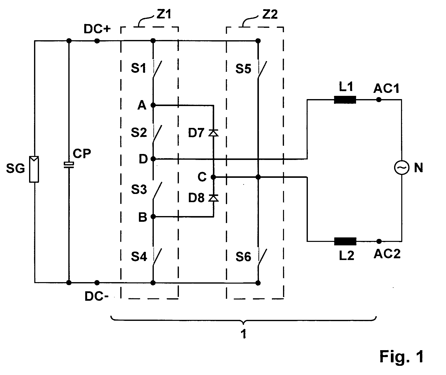
[0031]FIG. 1 shows a transformerless inverter 1 with considerably improved efficiency over prior art and with least operational leakage currents at the solar generator. In the FIGS. 1 through 7, switching symbols of mechanical switches were used in order to better illustrate the functioning principle of the circuit to be described.

[0032]The inverter 1 serves to convert an electrical direct voltage delivered by a photovoltaic generator SG into an alternating voltage for a current grid N. The inverter 1 has a direct voltage input with the terminals DC+ and DC− and an alternating voltage output with the terminals AC1 and AC2.

[0033]Downstream of the generator SG having a buffer capacitor CP as an intermediate circuit there is connected an arrangement consisting of six semiconductor switching elements S1 through S6 and two diodes D7 and D8. The switching elements S1 through S6 are arranged for two bridge branches Z1, Z2 to form, which are connected in parallel with the generator SG or wi...


PUM


Abstract

On an inverter (1) for converting an electric direct voltage, in particular of a photovoltaic direct voltage source into an alternating voltage with a direct voltage input with two terminals (DC+, DC−) and one alternating voltage output with two terminals (AC1, AC2) and with one bridge circuit including semiconductor switching elements (S1-S6), said bridge circuit comprising one first bridge branch (Z1) including four switching elements (S1-S4) and one second bridge branch (Z2) including two additional switching elements (S5, S6) as well as a freewheeling circuit provided with additional diodes (D7, D8), the efficiency is further increased without high frequency interferences and capacitive leakage currents having the possibility to occur on the generator side. This is achieved in that a respective one of the freewheeling diodes (D7, D8) forms a freewheeling branch together with a respective one of the switching elements (S2, S3) located in the first bridge branch (Z1), said freewheeling branch carrying a freewheeling current in a condition decoupled from the direct voltage.

Description

FIELD OF THE INVENTION[0001]The invention relates to an inverter for converting an electric direct voltage, more specifically a photovoltaic direct voltage source into an alternating voltage with a direct voltage input with two terminals between which there is provided a bridge circuit arranged in parallel, grid chokes being provided at the alternating voltage outputs of said bridge circuit, and with an alternating voltage output with two terminals.[0002]The invention is not only limited to photovoltaic plants but also finds application in batteries and other direct voltage generators.[0003]High efficiency but also safety aspects such as protection against high voltages are important when current is generated by photovoltaic plants.[0004]Since photovoltaic generators generate direct voltage, said direct voltage must be converted at mains frequency into a voltage of corresponding amplitude for feeding it into a public utility grid or into an island network. This calls for a suited in...

Claims


Application Information

Patent Timeline
Patent Type & Authority Applications(United States)
IPC IPC(8): H02M7/44
CPCH02M1/15H02M1/44H02M7/5388Y02E10/56H02M7/5387H02M7/48H02M7/521H02M7/515
Inventor BREMICKER, SVENGREIZER, FRANKVICTOR, MATTHIAS
Owner SMA SOLAR TECH AG
Why Eureka
Try Eureka