Video encoding apparatus and method using pipeline technique with variable time slot
- Summary
- Abstract
- Description
- Claims
- Application Information
AI Technical Summary
Benefits of technology
Problems solved by technology
Method used
Image

Examples
Embodiment Construction
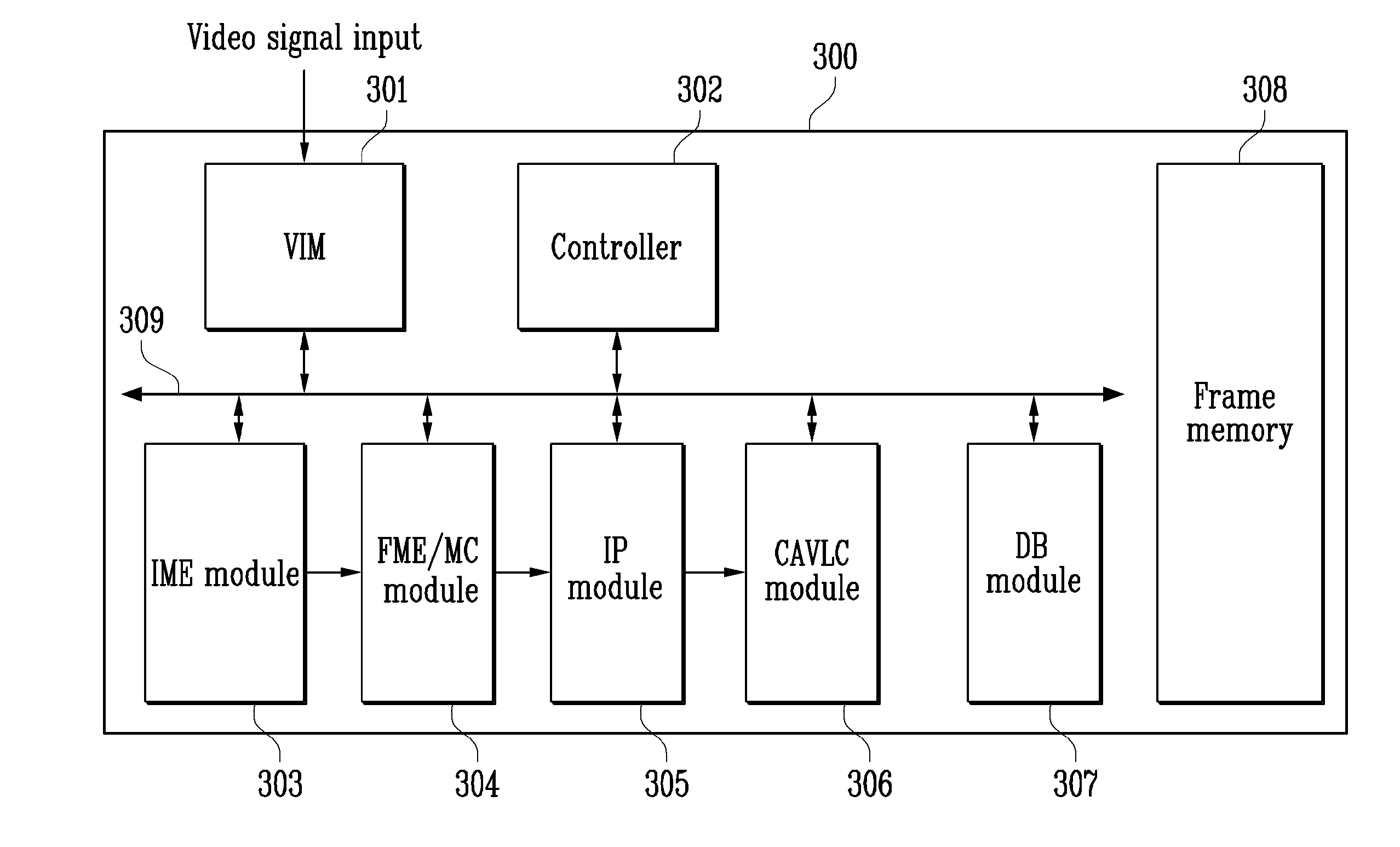
[0027]FIG. 3 is a block diagram showing a structure of a video encoding apparatus using a pipeline technique with a variable time slot according to an exemplary embodiment of the present invention.
[0028]Referring to FIG. 3, a video encoding apparatus 300 of the present invention includes a video input module (VIM) 301, controller 303, IME module 303, FME / MC module 304, IP module 305, CAVLC module 306, and DB module 307. The video encoding apparatus 300 further includes a frame memory 308 for storing input video signals and macroblocks and a data bus 309 for connecting the modules (blocks).
[0029]The VIM 301 is responsible for receiving digital video signals from an outside source and storing the received signals in units of macroblocks in the frame memory 308. The VIM 301 is responsible for receiving vertical and horizontal synchronization signals of the video signals and data bus signals and sending the received signals to functional blocks.
[0030]The controller 302 determines length...
PUM
 Abstract
Description
Claims
Application Information