Digital mobile communication system and transmission/reception method thereof

a mobile communication system and digital mobile technology, applied in the field of digital mobile communication system and transmission/reception method thereof, can solve the problems of inability to easily decide the position, shorten the substantial cp length, and deterioration of the final reception, so as to achieve the effect of using a cp

Inactive Publication Date: 2009-04-23
FUJITSU LTD
View PDF8 Cites 19 Cited by
  • Summary
  • Abstract
  • Description
  • Claims
  • Application Information

AI Technical Summary

Benefits of technology

[0016]Taking into consideration the problems described above, it is the object of the present invention to make it possible for a receiving station to effectively use a CP in an environment where there are both transmission stations that perf

Problems solved by technology

However, in the direct wave of path 1, the effective signal component of the OFDM symbol n is distorted at the tail end Ttail of the extraction interval, and furthermore, a signal from the adjacent OFDM symbol (n+1) is mixed in as interference, so the final reception deteriorates.
In that case, it is not possible to easily decide the position for extracting the received signal by the receiving station.
However, when the extraction interval is shifted forward, an adverse effect occurs in that the substantial CP length becomes shorter, so even when th

Method used


Image

  • Digital mobile communication system and transmission/reception method thereof
  • Digital mobile communication system and transmission/reception method thereof
  • Digital mobile communication system and transmission/reception method thereof

Examples


first embodiment

(A) First Embodiment

(a) Transmission Station

[0057]In a first embodiment of the invention, the case will be explained for a digital mobile communication system that uses the OFDM method in which a receiving station receives from a transmission station a signal for which window function processing has been performed, and demodulates that signal.

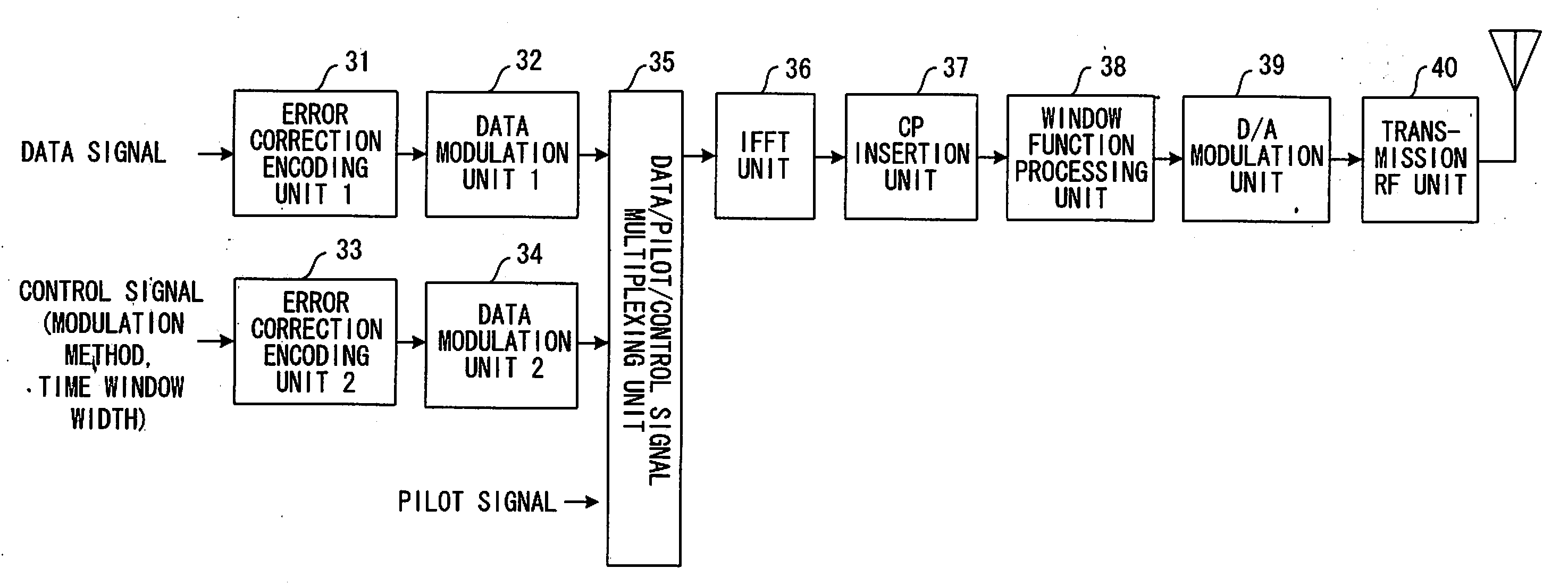
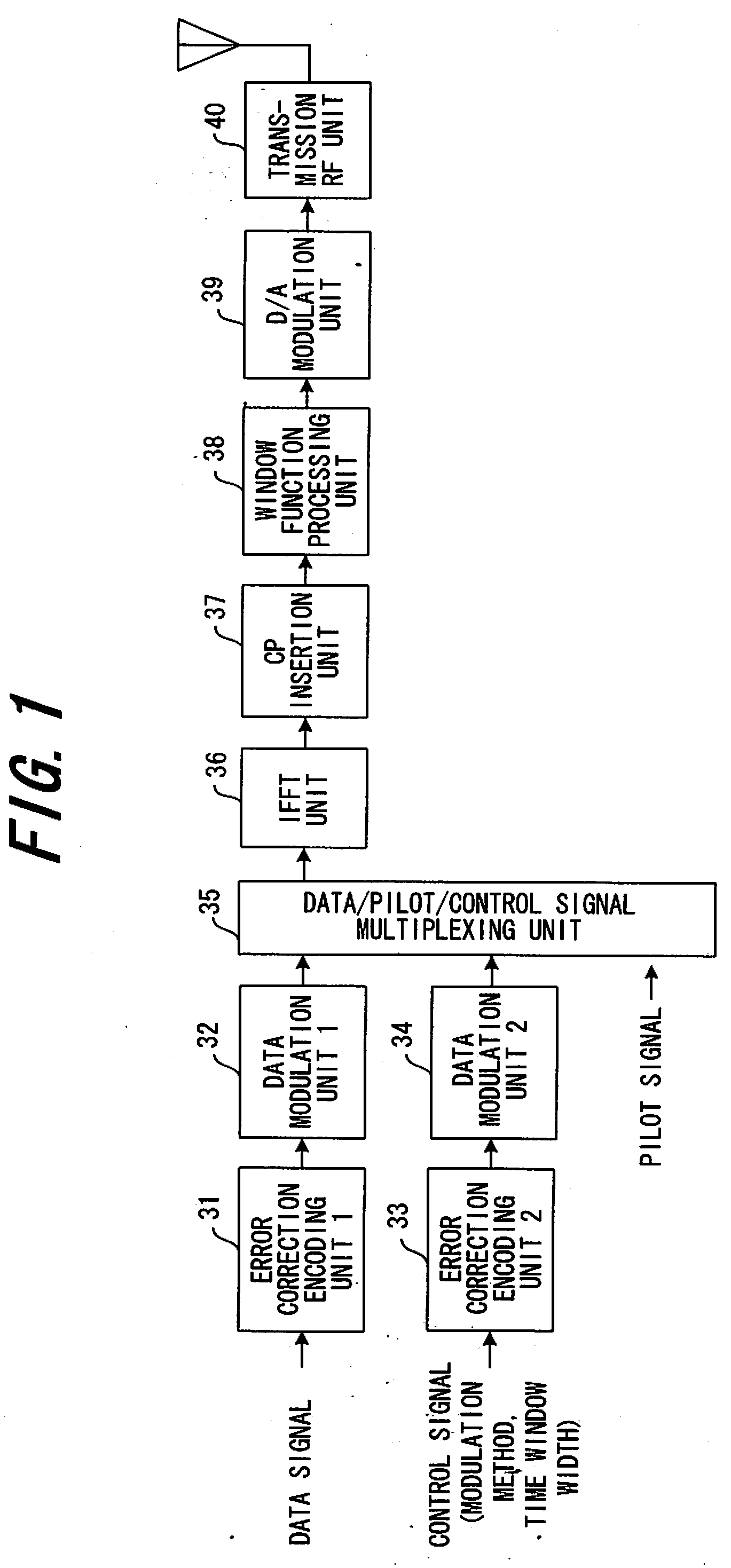
[0058]FIG. 1 is a block diagram of a transmission station of a first embodiment of the invention.

[0059]An error correction encoding unit 31 performs encoding of a data signal so that a receiver can perform error correction, and a data modulation unit 32 performs data modulation (for example, QPSK modulation) of the encoded data signal. On the other hand, an error correction encoding unit 33 performs data encoding of a control signal that includes information that indicates the window width of a window function processing that is applied by a window function multiplication unit (described later) and the data modulation method used, and a data mo...

second embodiment

(B) Second Embodiment

(a) Theory

[0076]FIG. 11 is a drawing showing the theory of a second embodiment of the invention. In the first embodiment, the reception timing Tr (see FIG. 8) was detected and the extraction position 2 of the effective signal component was shifted by Nwin / 2 forward from the reception timing. In this second embodiment of the invention, the extraction position of the effective signal component (called the reference extraction position) is fixed, and the reception timing is control led such that it is shifted by Nwin / 2 backward from the reference extraction position.

[0077]In other words, in this second embodiment, as shown in FIG. 11, reference target reception timing TT0 is set, and the start of the extraction position of the effective signal component is fixed at a position after the CP period Tcp from that timing TT0. Moreover, the actual reception timing Tr is control led so that the positional relationship between the reference extraction position and the actu...

third embodiment

(C) Third Embodiment

(a) Theory

[0095]FIG. 16 is a drawing for explaining the theory of a third embodiment of the present invention.

[0096]In the second embodiment, the receiving station calculates the time difference ΔT1 (=RT1−TT1) between a target reception timing TT1 and actual reception timing RT1, and sends that time difference ΔT1 to the transmission station as a transmission timing control value, then the transmission station controls the transmission timing so that ΔT1 becomes zero. In this third embodiment, the transmission station calculates the transmission control value ΔT1 itself, and controls the transmission timing so that ΔT1 becomes zero. However, the receiving station measures the time difference δT1 between the reference reception timing TT0 and the actual reception timing from each transmission station, and sends the result to each transmission station.

[0097]In order to execute the same transmission timing control as that executed in the second embodiment, a transmi...


PUM


Abstract

A radio communication system in which a transmission station performs window function processing on a transmission symbol to which cyclic prefixes have been attached for each specified number of samples, then transmits the signal, and a receiving station extracts and demodulates effective signal portions from the received signal, wherein the transmission station uses a control channel to notify the receiving station of window width Nwin of the window function; the receiving station adjusts the extraction position of the received signal based on the window width notified from the transmission station; and the receiving station uses the extracted received signal to execute demodulation processing of the transmission symbol. With this system, in an environment in which there are both transmission stations that perform window function processing on a transmission signal and transmission stations that do not perform window function processing, it is possible for the receiving station to effectively use cyclic prefixes CP and to perform demodulation without receiving the effect of distortion caused by the window function processing.

Description

CROSS REFERENCE TO RELATED APPLICATION[0001]This application is a continuation of PCT application of PCT / JP2006 / 313078, which was filed on Jun. 30, 2006.BACKGROUND OF THE INVENTION[0002]The present invention relates to a digital mobile communication system and transmission / reception method thereof, and more particularly to a digital mobile communication system and transmission / reception method thereof in which a transmission station and receiving station transmit or receive signals multiplied by an arbitrary time window.[0003]Transmission methods such as OFDM (Orthogonal Frequency Division Multiplex) that use FFT (Fast Fourier Transform) and CP (Cyclic Prefix) have been examined as radio access methods for next generation mobile communication. It is well know that the OFDM method has robustness to frequency selective broadband radio channels.[0004]The theory of the OFDM method will be explained below. FIG. 19 is a block diagram of a typical transmission station in the OFDM method. F...

Claims


Application Information

Patent Timeline
IPC IPC(8): H04L27/28
CPCH04L27/2607H04L27/2662H04W28/18H04W48/08H04L27/2688H04L25/03834H04L27/2646H04L27/2666H04W48/16H04L27/26265
Inventor JITSUKAWA, DAISUKESEKI, HIROYUKI
Owner FUJITSU LTD
Why Eureka
Try Eureka