Storage battery and insulating material and battery container using the same

a storage battery and insulating material technology, applied in the direction of cell sealing materials, cell components, cell component details, etc., can solve the problems of poor elasticity of resin, fine gap, leakage of electrolyte packed in the cylinder, etc., to prolong the life of storage batteries and improve elasticity. , the effect of poor elasticity

Inactive Publication Date: 2009-04-23
HONDA MOTOR CO LTD +1
View PDF5 Cites 12 Cited by
  • Summary
  • Abstract
  • Description
  • Claims
  • Application Information

AI Technical Summary

Benefits of technology

[0077]In the invention according to Claim 1, the annular member is formed by a rubber sheet. The rubber sheet is rich in elasticity and exhibits sealing properties and thus can maintain the sealing properties of the electrode rod piercing portion over an extended period of time, making it possible to prolong the lifetime of the storage battery.
[0078]The movement of the pressing member is restricted by a collar portion so that the rubber sheet cannot be excessively compressed.
[0079]In the invention according to Claim 2, the annular member is formed by a resin sheet the forward end of which has a slant provided thereon for pressing against an O-ring or liquid packing set at the base of the electrode rod.
[0080]The resin sheet is poor in elasticity and thus cannot be expected to have sealing properties. However, since the slant provided on the forward end of the resin sheet presses a

Problems solved by technology

A hard resin has a great strength but has a poor elasticity.
In addition, aluminum and resin differ from each other in physical properties such as heat expansion and thus form a fine gap when used over an extended period of time.
Due to external force, this fine gap grows to a great crack that causes the leakage of the electrolyte packed in the cylinder or other defects.
In this case, the current collecting plate, too, becomes an external force source and thus forms a fine gap between the resin and the metal and then causes this gap to grow to a great crack.
When such a crack is generated, the storage battery needs to be replaced, reducing the lifetime of the stora

Method used


Image

  • Storage battery and insulating material and battery container using the same
  • Storage battery and insulating material and battery container using the same
  • Storage battery and insulating material and battery container using the same

Examples


example 1

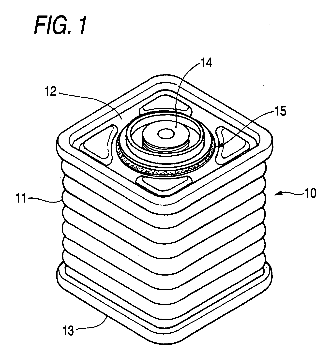
[0146]FIG. 1 is a perspective view of a storage battery according to the present invention and a storage battery 10 is a sealed case including a corrugated (wavy) cylinder 11 the upper opening of which is closed by a lid body 12 and the lower opening of which is closed by a bottom lid 13. The bottom lid 13 may be formed by deep drawing at the same time with the cylinder 11. The reference numeral 14 indicates an electrode rod and the reference numeral 15 indicates an annular member.

[0147]Explaining the lid body 12 (30) in FIG. 9, the lid body 12 (30) has a hole 16 formed therein at the center thereof and a plurality of through-holes 131 (37) formed therein surrounding this hole 16. These through-holes 131 (37) are formed to enhance the fixability of the annular member 15.

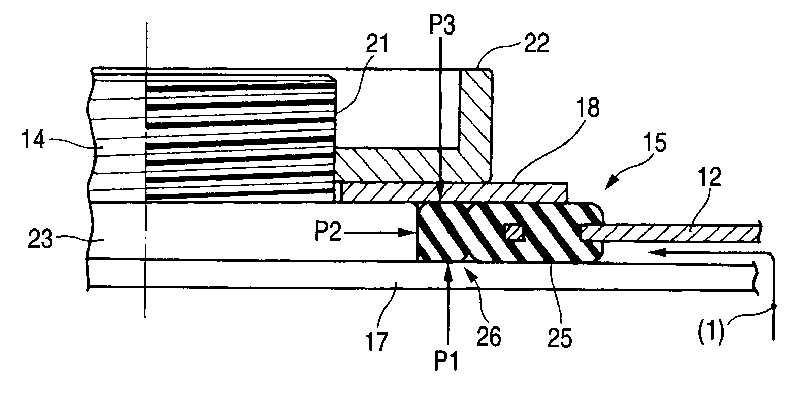
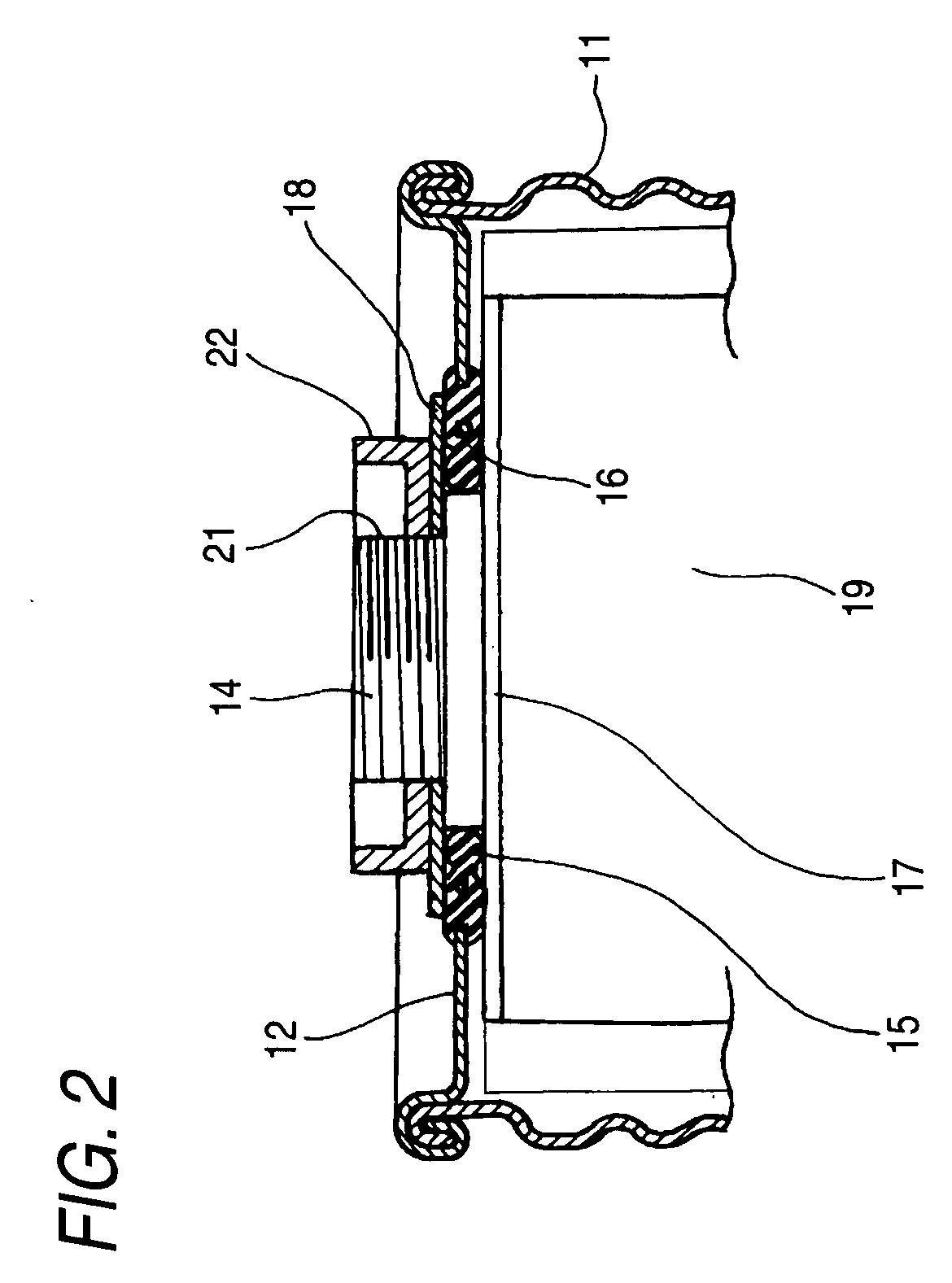
[0148]FIG. 2 is a sectional view of an essential part of the storage battery according to the present invention and depicts a structure including a lid body 12 having a hole 16 formed therein, an annular member 15 pr...

example 2

[0159]Another embodiment of implementation of the present invention will be described hereinafter.

[0160]FIG. 5 is a diagram illustrating another embodiment of FIG. 3 and includes a lid body 12 having a hole 16 formed therein, an annular member 15 provided surrounding this hole 16, a current collecting plate 17 disposed on one side (lower side as viewed on the drawing) of the lid body 12, an electrode rod 14 extending from this current collecting plate 17 arranged capable of protruding beyond the hole 16 and a pressing plate 18 disposed on the other side (upper side as viewed on the drawing) of the lid body 12.

[0161]And, the annular member 15 is formed by a resin sheet the forward end of which has a slant 28 provided thereon for pressing against an O-ring 27 set at the base of the electrode rod 14.

[0162]Further, the resin sheet is a hard resin which has a great strength but a poor stretchability.

[0163]FIG. 6 is a diagram illustrating the action of FIG. 5, the electrode rod 14 extends...

example 3

[0165]FIG. 7 is a diagram illustrating further embodiment of FIG. 3 and includes a lid body 12 having a hole 16 formed therein, an annular member 15 provided surrounding this hole 16, a current collecting plate 17 disposed on one side (lower side as viewed on the drawing) of the lid body 12, an electrode rod 14 extending from this current collecting plate 17 arranged capable of protruding beyond the hole 16 and a pressing plate disposed on the other side (upper side as viewed on the drawing) of the lid body 12.

[0166]And, the annular member 15 is formed by a resin sheet the forward end of which has a slant 28 provided thereon for pressing against a paint 29 made of a composition including PPT-based resin set at the base of the electrode rod 14.

[0167]Further, this resin sheet, too, is a hard resin which has a great strength but a poor stretchability as in the previous example.

[0168]FIG. 8 is a diagram illustrating the action of FIG. 7, the electrode rod 14 extends downward from the an...


PUM

PropertyMeasurementUnit
Temperatureaaaaaaaaaa

Abstract

A storage battery which can further intensify the sealing properties of the electrode rod piercing portion thereof, a technique capable of increasing the area of the sealing surface at the sealed portion of the storage battery, a technique capable of certainly preventing the missing of mounting of a rubber-based sealing material corresponding to O-ring at the sealed portion of the storage battery, and an insulating material having an excellent corrosion resistance to highly corrosive battery content and a battery container including same are provided.
An electrode rod 14 is allowed to extend upward through an annular member 15, a pressing member 18 is placed on the annular member 15, and a nut 22 is then threaded on a thread portion 21. This threading job is effected until the pressing member 18 is placed on and stopped by a collar portion 23. At the time when threading ends, a neck portion 25 is somewhat compressed to exhibit sealing properties. At the same time, a head portion 26 is drastically compressed and thus forms a first sealing portion at Point P1, a second sealing portion at Point P2 and a third sealing portion at Point P3. Further, while a disc sealing member 23 being properly compressed by the annular member 15 made of a resin and a current collecting plate 17, they are put in a vacuum heating furnace where they are then subjected to heat treatment at 160° C. in vacuo for 72 hours. This heat treatment allows PET film 25 to be heat-fused to the annular member 15 made of a resin and PET film 26 to be heat-fused to the current collecting plate 17. Moreover, a lid body 12 is formed integrally with an annular member 15 of rubber having a spindle-shaped section. And, this annular member 15 of rubber is bonded to PET film 32, 32 by the action of adhesive layer 33, 33. Since this bonding is firm, the annular member 15 of rubber cannot be detached from the lid body 12 during use.
Further, an insulating material for electrode mounting to be used in a battery container which is made of a polyethylene terephthalate resin and a container having a lid member obtained by forming a polyester resin-coated aluminum sheet double-seamed attached to the opening of the body of a can are provided, and a polyethylene terephthalate resin insulating material for electrode mounting is attached to a through-hole provided piercing the central part of the lid member with an adhesive including (B) a hardener made of at least one of phenolic resin, amino resin and polyisocyanate resin incorporated in (A) a polyester resin including a dicarboxylic acid component mainly including terephthalic acid and a glycol component and having a glass transition temperature of from 30° C. to 110° C., whereby the battery content has an excellent corrosion resistance to the electrolyte including a highly corrosive propylene carbonate salt as a main component, etc. and an enhanced leakage resistance.

Description

TECHNICAL FIELD[0001]The present invention relates to a technique for intensifying the sealing properties of the electrode rod through-hole of a storage battery.[0002]The present invention also relates to an insulating material excellent in resistance to corrosion with electrolyte and a battery container including same and more particularly to an insulating material made of a polyethylene terephthalate resin and a battery container having the insulating material attached to a lid member obtained by forming a polyester resin-coated aluminum sheet.BACKGROUND ART[0003]With the electrification / electronization of automobile devices, the use of chargeable products such as secondary battery, electrolytic capacitor and capacitor (referred to as “storage battery”) has increased.[0004]A storage battery has an electricity-storing element received in a sealed case from which electricity-storing element is withdrawn electric energy through an electrode and thus needs to have the electrode extend...

Claims


Application Information

Patent Timeline
IPC IPC(8): H01M2/06H01M2/08H01M2/04C08G63/127H01M50/184H01M50/186H01M50/193
CPCH01M2/0417H01M2/08H01M2/065Y02E60/10H01M50/154H01M50/186H01M50/191H01M50/184H01M50/193H01M50/172H01M50/147
Inventor YASUDA, NORIFUMIKATOH, HISASHIOYAMA, SHIGEKIKOMAZAWA, EISUKEMATSUMOTO, YASUHIROSASAKI, SHUJIMURAKAMI, KENICHIISHII, MASAYUKIFUJIMOTO, HIROSHIKURODA, KANJIYUI, YOSHIAKIMORIGA, TOSHINORIHIROTSU, MUNEMITSU
Owner HONDA MOTOR CO LTD
Why Eureka
Try Eureka