Wire Twisting Tool

Inactive Publication Date: 2009-04-30
CHRISTIAN WAYNE HARVEY
View PDF29 Cites 1 Cited by
  • Summary
  • Abstract
  • Description
  • Claims
  • Application Information

AI Technical Summary

Benefits of technology

[0014]It is a further advantage of the present invention to provide a wire twisting tool that can be used to rapidly produce a tight coil of twisted wire around a hanging wire, with minimal exertion required by the tool user.
[0015]It is a still further advantage of the present invention to provide a wire twisting tool that is easily stored by the tool user, when not in use.
[0016]The advantages set out hereinabove, as well as other objects and goals inherent thereto, are at least partially or fully provided by the wire twisting tool of the present invention, as set out herein below.
[0017]Accordingly, in one aspect, the present invention provides a wire twisting tool for use with wire ties used in supporting ceilings or ceiling comp

Problems solved by technology

The most apparent disadvantage of this technique is the cost of labour for the labour intensive task of twisting the wire.
In practise, because of the stiffness of the wire tie, it is difficult on the user to use his fingers to twist each wire tie around itself eight or ten times;—particularly when the total number of wire ties to be twisted in a larger ceiling installation can exceed several hundred, or more.
However, in practice, many workers in an abbreviated approach, will only twist the wire three or four times about itself in order to conserve time, and to conserve their finger strength.
Still, even when only two or three twists are made, the work is time consuming, and can tax the strength of the user's fingers and hands.
Further, while this abbreviated approach can save some time, this method of connecting the wire to the bracket is not very secure.
Under sufficient stress, the abbreviated wire twist can stretch, and under further stress, the wire can prematurely untwist.
Still another disadvantage of this abbreviated approach is that the connection between the wire tie and the ceiling or ceiling fixture is looser than designed.
However, in the case of an earthquake, fire or th

Method used


Image

  • Wire Twisting Tool
  • Wire Twisting Tool
  • Wire Twisting Tool

Examples


second embodiment

[0036]FIG. 7 is a perspective view of a tool according to the present invention; and

third embodiment

[0037]FIG. 8 is a cross-sectional view of a tool according to the present invention.

DETAILED DESCRIPTION OF THE PREFERRED EMBODIMENTS

[0038]The novel features which are believed to be characteristic of the present invention, as to its structure, organization, use and method of operation, together with further objectives and advantages thereof, will be better understood from the following drawings in which a presently preferred embodiment of the invention will now be illustrated by way of example only. In the drawings, like reference numerals depict like elements, and where appropriate, recessed parts or openings are shown in outline.

[0039]It is expressly understood, however, that the drawings are for the purpose of illustration and description only and are not intended as a definition of the limits of the invention.

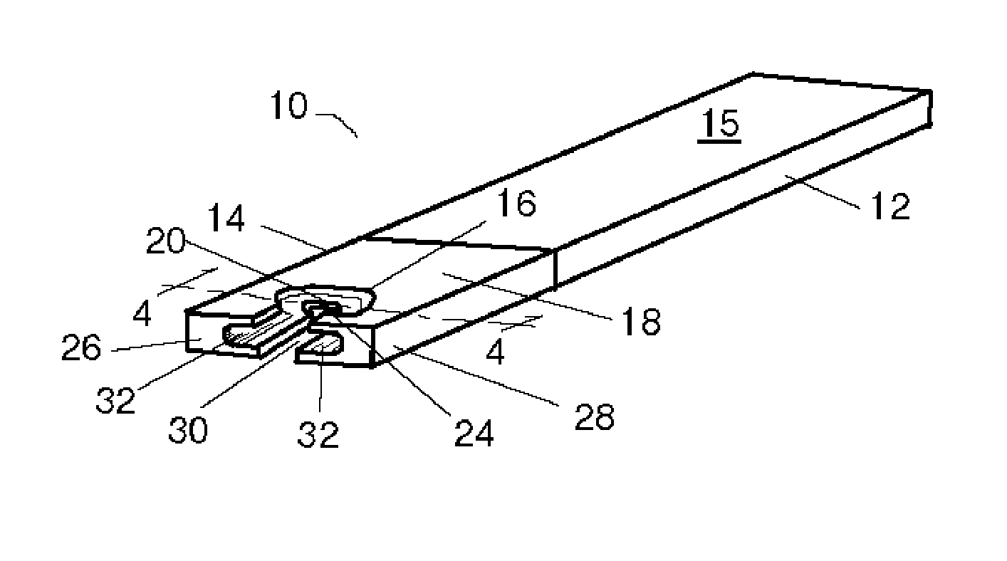
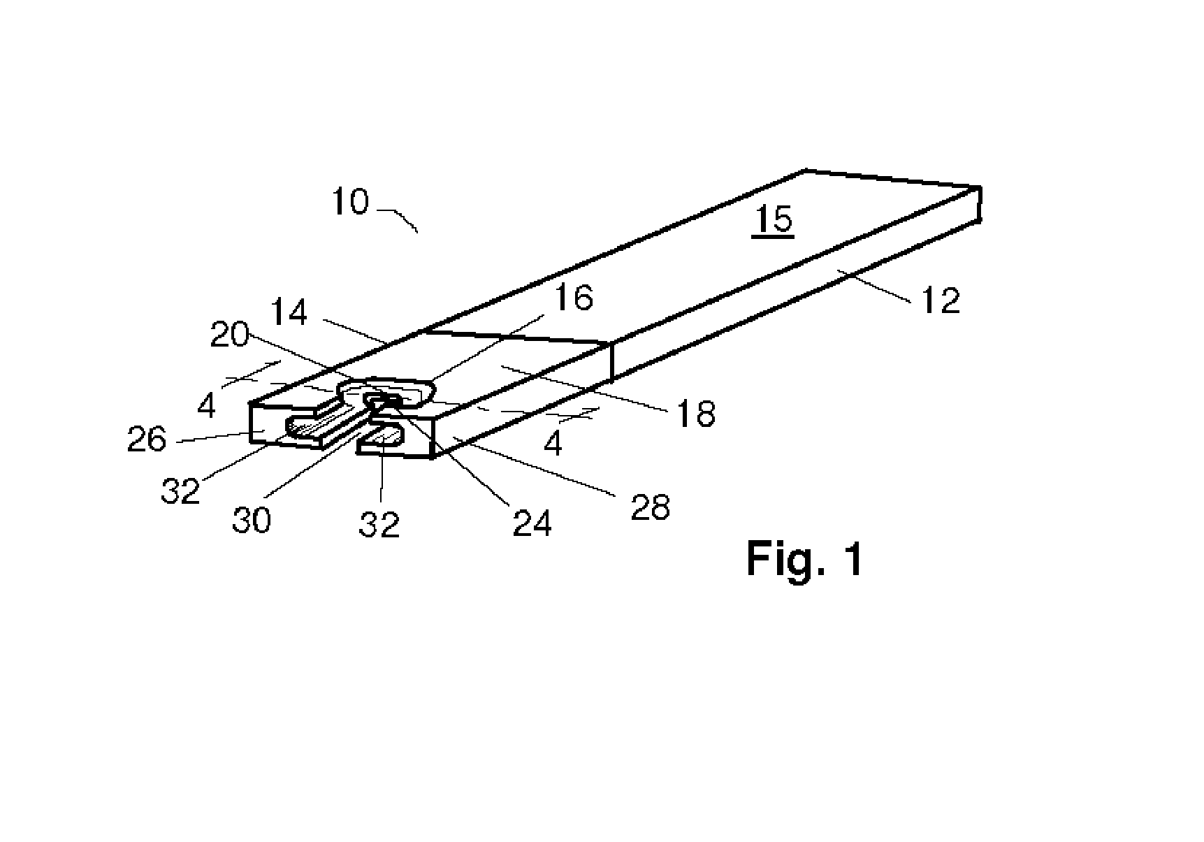
[0040]Referring to FIG. 1, a tool according to the present invention 10 is shown and has a handle section 12 which is integrated with tool section 14. Tool 10 is preferabl...


PUM

PropertyMeasurementUnit
Angleaaaaaaaaaa
Diameteraaaaaaaaaa
Diameteraaaaaaaaaa

Abstract

A wire twisting tool is provided which is adapted to be used in the installation of wire ties that are used to support a building ceiling, or other ceiling components such as piping, HVAC equipment, or the like. The tool has a central passageway through which a hanging section of wire tie can pass, a oval, coil forming recess around the passageway to allow for the formation of a wire tie coil around the hanging section, and grooved slots extending from the passageway to the end or edge of the tool, to pull or push a free end of the wire tie around the hanging section. Using the tool, an operator can rapidly produce a tight, coil of material around the hanging section, with minimal exertion.

Description

FIELD OF THE INVENTION[0001]The present invention relates to the field of tools, and in particular, relates to a tool for twisting the wire ties which are used to hang suspended ceilings and / or other various ceiling components, such as light fixtures, fans, and the like.BACKGROUND OF THE INVENTION[0002]Current practice in the construction trade and building industry is to suspend ceiling tiles, acoustic ceiling tiles, fixtures, and the like, with wire ties that are fastened at one end to a bracket which is affixed to building structure such as a ceiling joist, a concrete or masonry pad used to form the roof or floor above, a ceiling panel support grid, and / or brackets affixed to these surfaces. Typically, one end of the wire ties is attached to the support structure and the other end hangs down from this structure. The wire ties are commonly made of from 8 to 12 gauge steel, or the like, and is reasonably resilient in order to provide the strength needed to support the weight of the...

Claims


Application Information

Patent Timeline
IPC IPC(8): B21F33/00B21F7/00
CPCE04B9/18
Inventor CHRISTIAN, WAYNE HARVEY
Owner CHRISTIAN WAYNE HARVEY
Why Eureka
Try Eureka