Tension member for an elevator

Inactive Publication Date: 2009-04-30
BARANDA PEDRO S +2
View PDF80 Cites 3 Cited by
  • Summary
  • Abstract
  • Description
  • Claims
  • Application Information

AI Technical Summary

Benefits of technology

[0009]A principal feature of the present invention is the flatness of the tension member. The increase in aspect ratio results in a tension member that has an engagement surface, defined by the width dimension, that is optimized to distribute the rope pressure. Therefore, the maximum pressure is minimized within the tension member. In addition, by increasing the aspect ratio relative to a round rope, which has an aspect ratio equal to one, the thickness of the tension member may be reduced while maintaining a constant cross-sectional area of the tension member.
[0011]As a result of the configuration of the tension member, the rope pressure may be distributed more uniformly throughout the tension member. As a result, the maximum rope pressure is significantly reduced as compared to a conventionally roped elevator having a similar load carrying capacity. Furthermore, the effective rope diameter ‘d’ (measured in the bending direction) is reduced for the equivalent load bearing capacity. Therefore, smaller values for the sheave diameter ‘D’ may be attained without a reduction in the D / d ratio. In addition, minimizing the diameter D of the sheave permits the use of less costly, more compact, high speed motors as the drive machine without the need for a gearbox.
[0012]In a particular embodiment of the present invention, the individual cords are formed from strands of metallic material. By incorporating cords having the weight, strength, durability and, in particular, the flexibility characteristics of appropriately sized and constructed materials into the tension member of the present invention, the acceptable traction sheave diameter may be further reduced while maintaining the maximum rope pressure within acceptable limits. As stated previously, smaller sheave diameters reduce the required torque of the machine driving the sheave and increase the rotational speed. Therefore, smaller and less costly machines may be used to drive the elevator system.
[0013]In a further particular embodiment of the present invention, a traction drive for an elevator system includes a tension member having an aspect ratio greater than one and a traction sheave having a traction surface configured to receive the tension member. The tension member includes an engagement surface defined by the width dimension of the tension member. The traction surface of the sheave and the engagement surface are complementarily contoured to provide traction and to guide the engagement between the tension member and the sheave. In an alternate configuration, the traction drive includes a plurality of tension members engaged with the sheave and the sheave includes a pair of rims disposed on opposite sides of the sheave and one or more dividers disposed between adjacent tension members. The pair of rims and dividers perform the function of guiding the tension member to prevent gross alignment problems in the event of slack rope conditions, etc.
[0014]In a still further embodiment, the traction surface of the sheave is defined by a material that optimizes the traction forces between the sheave and the tension member and minimizes the wear of the tension member. In one configuration, the traction surface is integral to a sheave liner that is disposed on the sheave. In another configuration, the traction surface is defined by a coating layer that is bonded to the traction sheave. In a still further configuration, the traction sheave is formed from the material that defines the traction surface.

Problems solved by technology

Although conventional round steel ropes and cast iron sheaves have proven very reliable and cost effective, there are limitations on their use.
One such limitation is the traction forces between the ropes and the sheave.
Both techniques reduce the durability of the ropes, however, as a result of the increased wear (wrap angle) or the increased rope pressure (undercutting).
Another limitation on the use of round steel ropes is the flexibility and fatigue characteristics of round steel wire ropes.
Another drawback of conventional round ropes is that the higher the rope pressure, the shorter the life of the rope.

Method used


Image

  • Tension member for an elevator
  • Tension member for an elevator
  • Tension member for an elevator

Examples


Embodiment Construction

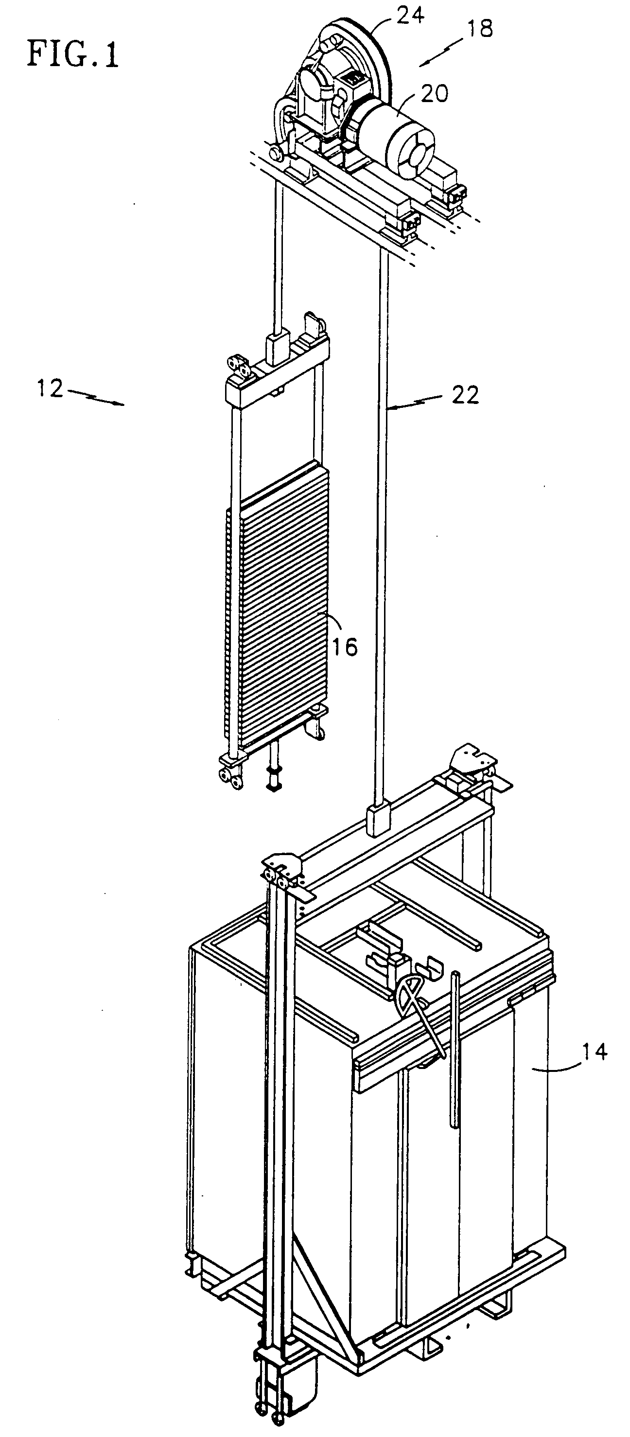
[0025]Illustrated in FIG. 1 is a traction elevator system 12. The elevator system 12 includes a car 14, a counterweight 16, a traction drive 18, and a machine 20. The traction drive 18 includes a tension member 22, interconnecting the car 14 and counterweight 16, and a traction sheave 24. The tension member 22 is engaged with the sheave 24 such that rotation of the sheave 24 moves the tension member 22, and thereby the car 14 and counterweight 16. The machine 20 is engaged with the sheave 24 to rotate the sheave 24. Although shown as an geared machine 20, it should be noted that this configuration is for illustrative purposes only, and the present invention may be used with geared or gearless machines.

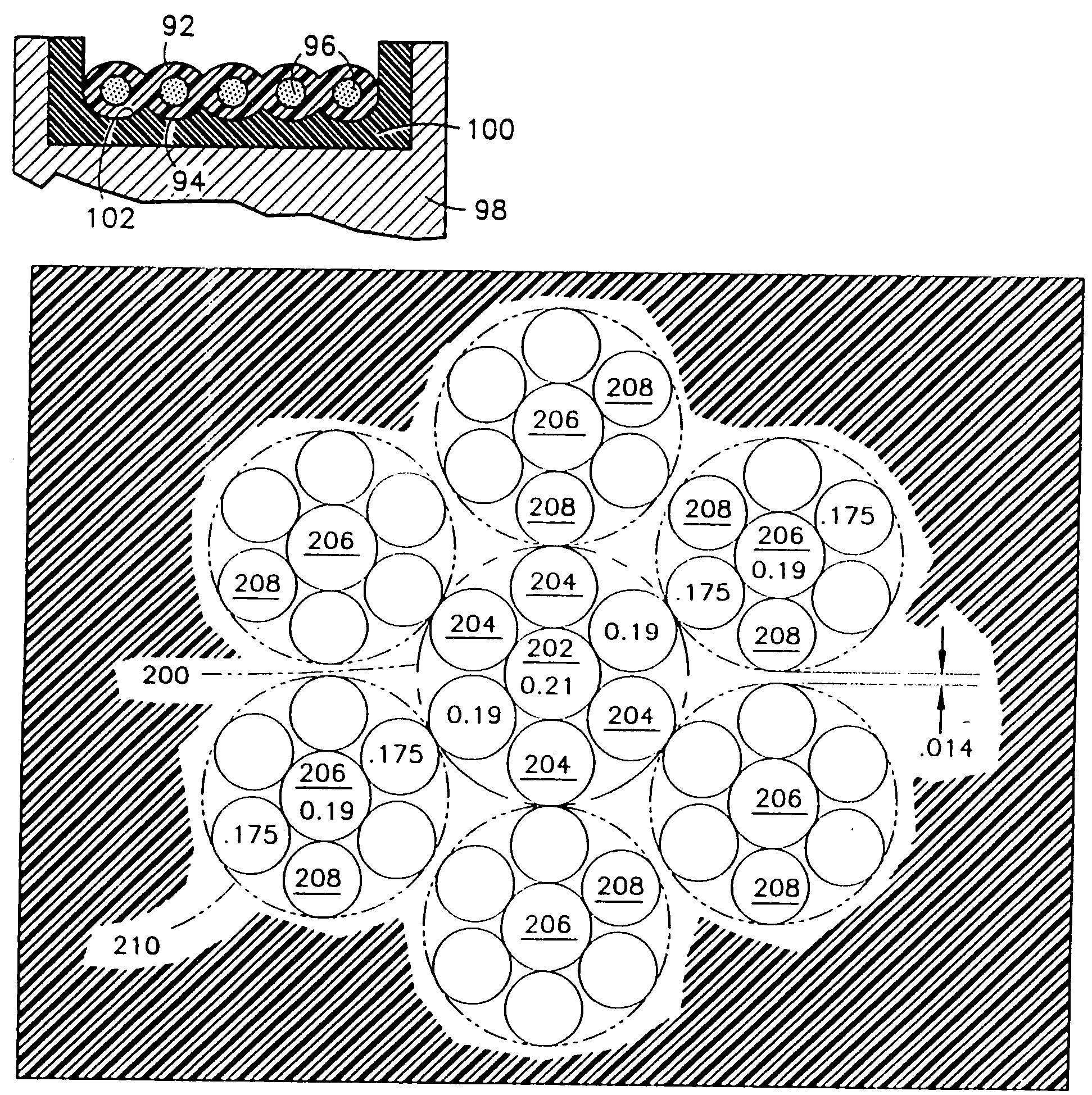
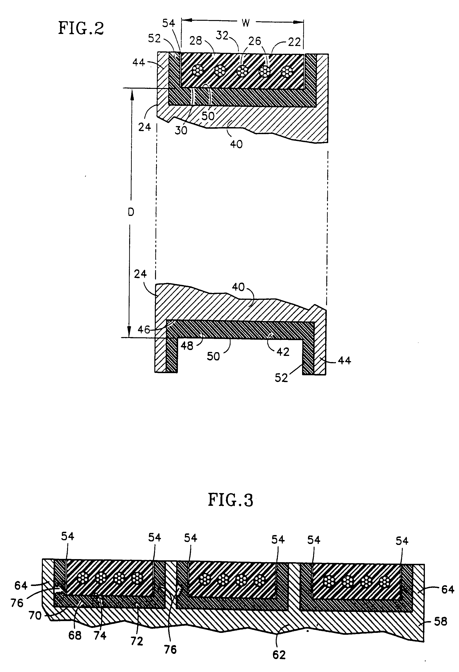
[0026]The tension member 22 and sheave 24 are illustrated in more detail in FIG. 2. The tension member 22 is a single device that integrates a plurality of cords 26 within a common coating layer 28. Each of the cords 26 is formed from preferably seven twisted strands, each made up of s...


PUM

PropertyMeasurementUnit
Shapeaaaaaaaaaa
Metallic bondaaaaaaaaaa
Tensionaaaaaaaaaa

Abstract

A tension member for an elevator system has an aspect ratio of greater than one, where aspect ratio is defined as the ratio of tension member width w to thickness t (w / t). The increase in aspect ratio results in a reduction in the maximum rope pressure and an increased flexibility as compared to conventional elevator ropes. As a result, smaller sheaves may be used with this type of tension member. In a particular embodiment, the tension member includes a plurality of individual load carrying cords encased within a common layer of coating. The coating layer separates the individual cords and defines an engagement surface for engaging a traction sheave.

Description

CROSS REFERENCE TO RELATED APPLICATIONS[0001]This is a continuation-in-part of U.S. Ser. No. 09 / 031,108 filed Feb. 26, 1998, the entirety of which is incorporated herein by reference.TECHNICAL FIELD[0002]The present invention relates to elevator systems, and more particularly to tension members for such elevator systems.BACKGROUND OF THE INVENTION[0003]A conventional traction elevator system includes a car, a counterweight, two or more ropes interconnecting the car and counterweight, a traction sheave to move the ropes, and a machine to rotate the traction sheave. The ropes are formed from laid or twisted steel wire and the sheave is formed from cast iron. The machine may be either a geared or gearless machine. A geared machine permits the use of higher speed motor, which is more compact and less costly, but requires additional maintenance and space.[0004]Although conventional round steel ropes and cast iron sheaves have proven very reliable and cost effective, there are limitations...

Claims


Application Information

Patent Timeline
IPC IPC(8): B66B11/08B66B7/02B66B7/06D07B1/22B66B7/08B66B7/10B66B9/00B66B9/02B66B11/00B66B13/30B66B15/04B66B17/12D07B1/06D07B1/16
CPCB66B7/06B66B7/062B66B9/00B66B11/004B66B11/08Y10S254/902D07B1/0673D07B1/22D07B2201/2087D07B2401/205D07B2501/2007B66B15/04D07B2205/2064D07B2801/22D07B1/16
Inventor BARANDA, PEDRO S.MELLO, ARY O.O'DONNELL, HUGH J.
Owner BARANDA PEDRO S
Why Eureka
Try Eureka