Heating element for an internal combustion engine

a technology of internal combustion engine and heating element, which is applied in the field of heating element, can solve the problems of many people's discomfort in driving a vehicle, the sensor cannot help to control the emissions, and the difficulty of bringing the automobile up to the operating temperature, so as to improve the automobile industry

Inactive Publication Date: 2009-04-30
TESTA MATTHEW
View PDF6 Cites 33 Cited by
  • Summary
  • Abstract
  • Description
  • Claims
  • Application Information

AI Technical Summary

Benefits of technology

[0016]It is another object of the present invention to prevent pollutants from being unnecessarily released into the environment.
[0017]It is yet a further object of the present invention to save automobile users money by decreasing the amount of fuel required to bring an automobile up to operating temperature.
[0020]Typically, the heating element is a metallic tubular member. To raise the temperature of the passenger compartment quicker, the second end of the transected hose feeds an inlet opening to a heater core of the internal combustion engine heating system.

Problems solved by technology

Until the engine reaches a closed loop these sensors cannot help to control the emissions.
In colder climates throughout the world many people have a difficult time in bringing their automobiles up to operating temperature during the winter months.
It is also uncomfortable to drive a vehicle that forces cold air through its heating system during the winter months.
When the oil is still cold, the piston struggles to move up and down thus causing unwanted deformed strokes, which shortens the life of the engine.
One problem with this is that remote starter are often unreliable thereby forcing the driver to walk to his vehicle, start the vehicle, return to the house and still wait for the vehicle to warm.
Remote starters often cause severe electrical problems to the automobile after prolonged use.
As a wire corrodes from exposure after being cut, costly electrical problems quickly arise.
Another problem with allowing a vehicle to achieve operating temperature is that a significant amount of fuel is wasted.
Wasting fuel not only costs money, but it releases unnecessary pollutants into the environment, thus contributing to global warming.

Method used


Image

  • Heating element for an internal combustion engine
  • Heating element for an internal combustion engine
  • Heating element for an internal combustion engine

Examples


Embodiment Construction

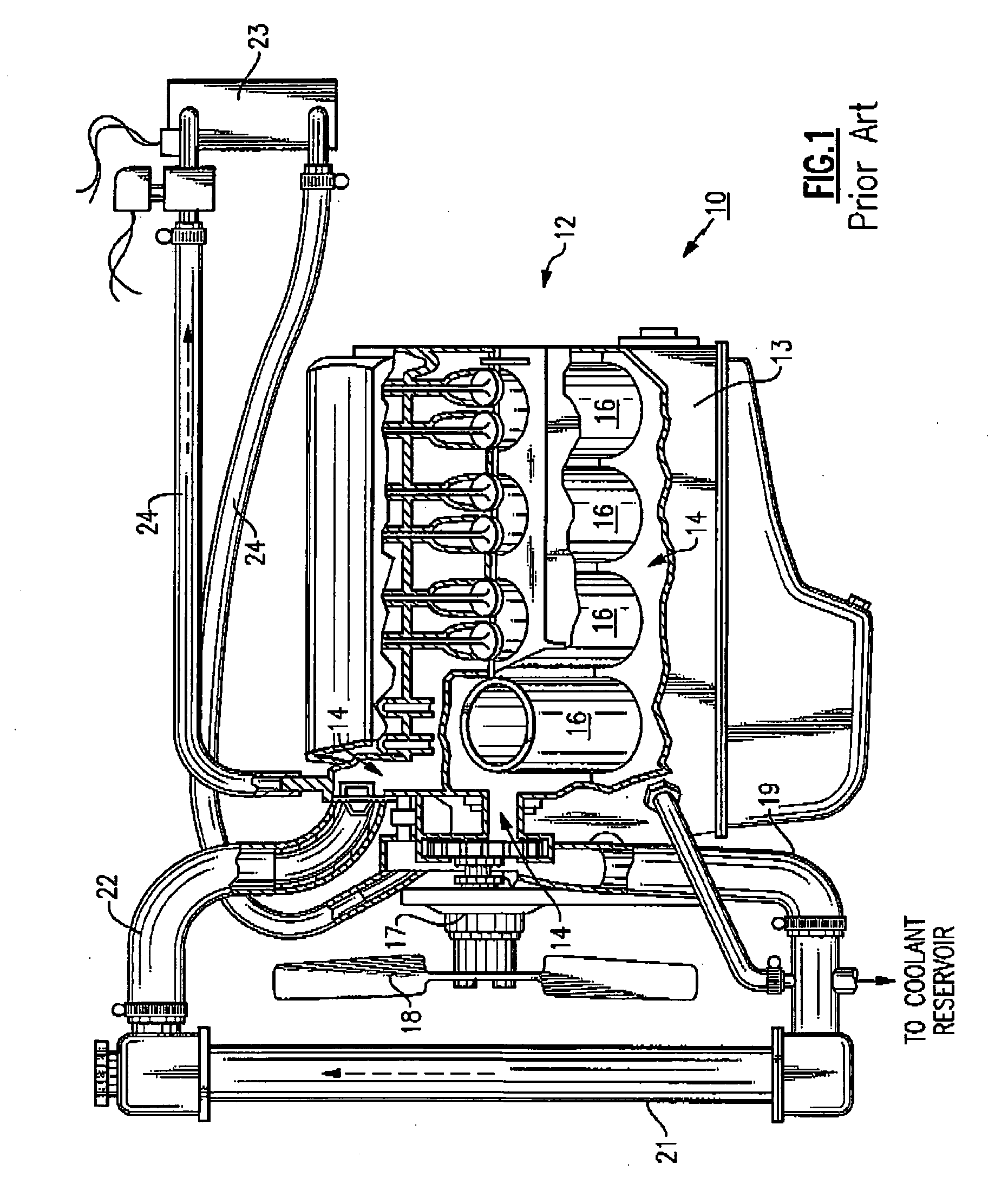
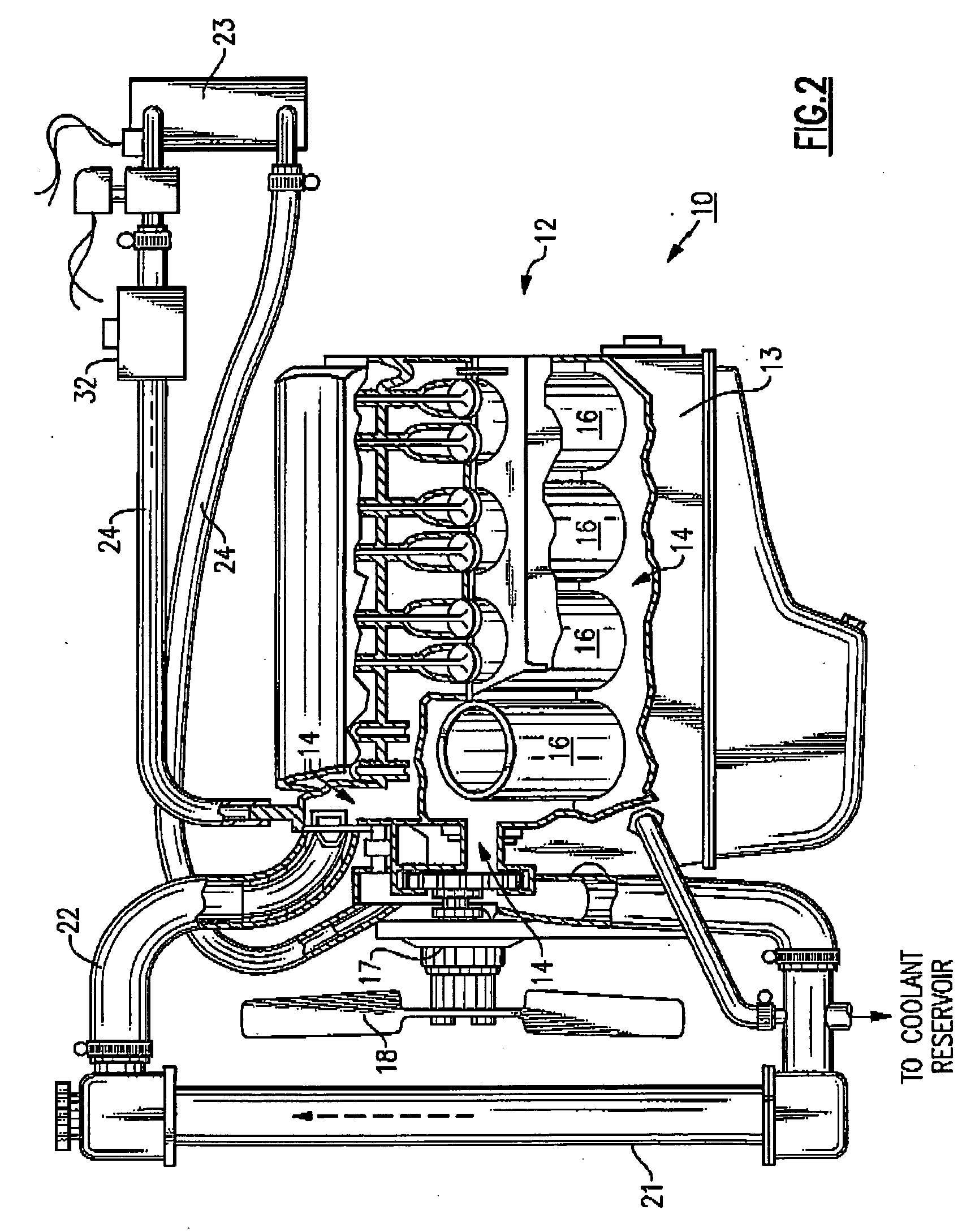
[0031]Referring now to FIG. 1, there is shown a heating system 10 for a fluid cooled internal combustion engine 12. The engine 12 includes a block 13 having a jacket, or plurality of passages 14 for heating system fluid formed therein. The passages 14 are disposed about the cylinders 16 of the engine 12. The passages 14 communicate with a water pump 17 and fan 18 structure and with the return 19 to a radiator 21. A hose 22 disposed away from the return 19 extends between the radiator 21 and the passages 14 within the engine block 13. The heater core 23 is connected by hoses 24 to the passages 14.

[0032]As the engine 12 runs it heats up by itself to an operating temperature. Heating system fluid flows through the passages 14 over the heating engine 12 thus raising the temperature of the heating system fluid.

[0033]At the heater core 23, the heating system fluid passes through a series heater core tubes (not depicted) which are connected to heat transfer fins, thus raising the temperatu...


PUM


Abstract

The present invention provides a method and apparatus to quickly raise the temperature of an internal combustion engine and the temperature of the ambient air in a passenger compartment of a vehicle. The apparatus comprises a heating element that quickly realizes a temperature of approximately 300 degrees F. Heating system fluid flows across this heating element which raises the temperature of the heating system fluid. This now heated heating system fluid flows through heater core tubes which are connected to heater core fins, thus raising the ambient temperature air which is blown over the heater core fins and into the passenger compartment. The heated heating system fluid also flows over the engine thus helping to raise the operating temperature of the engine.

Description

FIELD OF THE INVENTION[0001]The present invention relates generally to the field of automobiles and, more particularly, to a heating element which assists in heating automobile components of an internal combustion engine and forced air at start up.BACKGROUND OF THE INVENTION[0002]Automobiles use a cooling system to help maintain engine temperature and to regulate open and closed loop emission systems. For emission systems to become effective the engine must be up to temperature. The emission system regulates unwanted gases from the motor and through an exhaust system. Some emission include carbon monoxide, carbon dioxide, hydrocarbons and oxides of nitrogen. Engines use many different sensors and a control system to force an engine into a closed loop system.[0003]The sensors include oxygen sensors for monitoring exhaust temperature and oxygen content; ECT sensor for monitoring the engine coolant temperature; manifold pressure sensor for measuring the engine vacuum within the motor. ...

Claims


Application Information

Patent Timeline
Patent Type & Authority Applications(United States)
IPC IPC(8): H05B3/02F02N17/04F02N19/04
CPCB60H1/034B60H1/2221F02N19/10F01P2037/02F01P2060/08F01P2011/205
Inventor TESTA, MATTHEW
Owner TESTA MATTHEW
Why Eureka
Try Eureka