Controlled growth of a nanostructure on a substrate

a nanostructure and controlled growth technology, applied in the field of nanostructures, can solve the problems of inability to achieve perfect control, and increase the cost of new materials

Active Publication Date: 2009-04-30
SMOLTEK AB
View PDF21 Cites 36 Cited by
  • Summary
  • Abstract
  • Description
  • Claims
  • Application Information

AI Technical Summary

Benefits of technology

[0035]By having a layer of material between the catalyst and the substrate, it is possible to influence the texture

Problems solved by technology

Relentless efforts at miniaturization are bringing traditional CMOS devices to the limit where the device characteristics are governed by quantum phenomena; in such regimes, perfect control is impossible to achieve.
Consequently, the problems associated with the physical and electrical characteristics of traditional materials used for making devices have escalated.
The choice of new materials is however limited by factors such as compatibility with existing production methods, reproducibility of manufacture and cost.
High power consumption due to leakage current: currently, the device performance is degraded due to high leakage current through gate oxide (which is very thin).
This in turn increases the leakage current in the off state, and hence increases power consumption, which in turn reduces the life time of a battery.
Poor performance of Cu interconnects: due to its low resistivity, copper is used for making interconnects that are used for connecting various components to one another, as well as devices and circuits with the outside world.
Due to the dramatic reduction in the size of the components, interconnects based on copper material are now showing poor performance in terms of current carrying capacity and lifetime of the wires.
This in turn reduces the lifetime of a processor.
No solution currently exists for interconnects that will efficiently connect the devices in a circuit with those outside of the circuit, in time to meet the projected demand for current density over the next several years.
Creating such high aspect ratio contacts with straight walls poses substantial technological challenges, not least because void-free filling with metals (also known as vias) of such high aspect ratio features is extremely difficult.
High heat dissipation: modern microprocessors generate inordinate amounts of heat.
In particular, for example, copper interconnects of the sizes required for current and future devices generate so much heat that their electrical resistance is increased, thereby leading to a decreased capacity to carry current.
However a practical solution for cooling of such systems which will not eventually exceed the power budget for processors has yet to be found

Method used


Image

  • Controlled growth of a nanostructure on a substrate
  • Controlled growth of a nanostructure on a substrate
  • Controlled growth of a nanostructure on a substrate

Examples


example 1

Electron-Beam Writer

[0189]FIG. 25 shows a SEM image of an embodiment of an electron beam writer that may be used as a nano writer, wherein: DCNT=Diameter of CNT / CNF / nano-structure; LSD=thickness of insulator; LCNT=Length of CNT / CNF / nanostructure; Lg=Distance between CNT / CNF / nanostructure and electrodes; FElas=Elastostatic force acting on CNT / CNF / nanostructure; FElec=Electrostatic force; and FvdW=Van der Waals force. The voltage source in FIG. 25 may be DC or AC source depending on application.

[0190]The structure in FIG. 25 may also be used as an electron beam emitter for use in a display, wherein the position of the nanostructure is controlled while electrons are emitted from the structure onto, for instance, a fluorescent screen that emits photons when excited by electrons, thus providing a visible point. In this way, a display unit (pixel) with localized geometry control (sub pixels) is provided. By forming a plurality of these display units into a system of electron beam emitters...

example 2

Control

[0192]This example presents results that evidence control over the morphology and control over the chemical composition present at the base and the tip of grown carbon nanostructures, see FIGS. 26A and 26B. FIG. 26A is a transmission electron microscopy (TEM) micrograph showing a carbon nanofiber grown on a W metal underlayer. FIG. 26A shows how the morphology can differ based on sample preparation recipe.

[0193]FIG. 26B shows an example of how the chemical composition at the interface (base) and at the tip can be obtained. In FIG. 26B panel (a) there is a TEM image of a grown carbon nanofiber; in panel (b) an EDS spectrum shows the chemical elements at the tip of the fibers (catalyst region); and in panel (c) an EDS spectrum shows the chemical elements at the base of the fibers (underlayer region).

[0194]The CNF grew from a flat catalyst surface and no significant catalyst film break up was observed (see, e.g., Kabir, M. S.; Morjan, R. E.; Nerushev, O. A.; Lundgren, P.; Bengts...

example 3

Incorporating Nanostructures into a CMOS Device

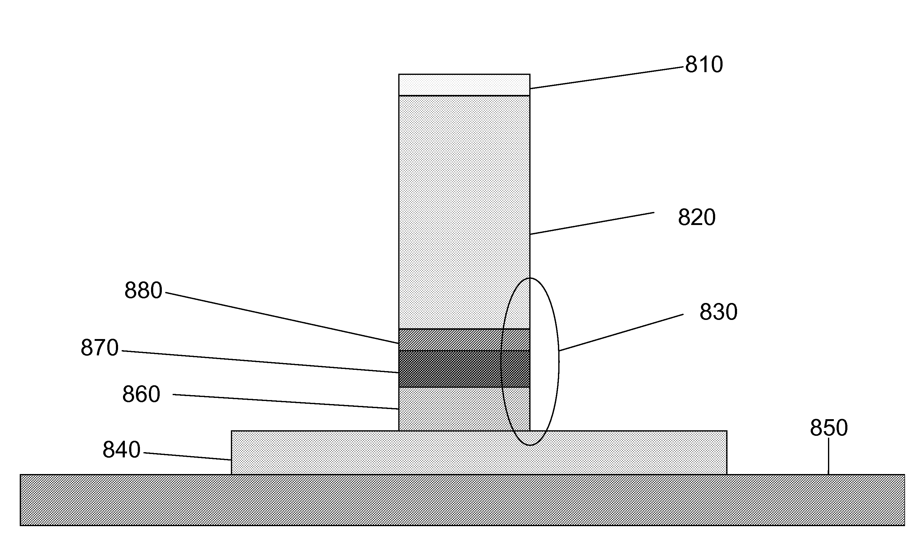
[0195]Nanostructures as described herein can be incorporated into a CMOS device as vertical interconnects. To accomplish this, a filler layer such as an insulator is deposited over a substrate and the nanostructures situated thereon, and then polished / etched back until the nanostructure is exposed at the top. The catalyst layer can be removed, e.g., by etching, once the nanostructure is grown if required.


PUM

PropertyMeasurementUnit
Thicknessaaaaaaaaaa
Thicknessaaaaaaaaaa
Angleaaaaaaaaaa

Abstract

The present invention provides for nanostructures grown on a conducting substrate, and a method of making the same. The nanostructures grown according to the claimed method are suitable for manufacturing electronic devices such as an electron beam writer, and a field emission display.

Description

CLAIM OF PRIORITY[0001]This application claims the benefit of priority of Swedish provisional application serial no. 0500926-1, filed Apr. 25, 2005, and of Swedish provisional application serial no. 0501888-2, filed Aug. 25, 2005, and to U.S. provisional application Ser. No. 60 / 772,449, filed Feb. 10, 2006, all of which are incorporated herein by reference in their entirety.FIELD OF THE INVENTION[0002]The present invention generally relates to nanostructures and methods for their growth. The present invention more particularly relates to methods of controlling the growth of nanostructures such as carbon nanofibers which enables manufacture of electron emission based devices such as electron beam writers and field emission displays.BACKGROUND[0003]Relentless efforts at miniaturization are bringing traditional CMOS devices to the limit where the device characteristics are governed by quantum phenomena; in such regimes, perfect control is impossible to achieve. This has engendered a ne...

Claims


Application Information

Patent Timeline
IPC IPC(8): H01L29/66H01L21/20
CPCB82Y10/00Y10S977/827B82Y40/00C01B31/0233C01B2202/34C01B2202/36C23C16/04C23C16/26D01F9/08D01F9/127H01J1/304H01J3/022H01J9/025H01J2201/30469H01J2237/31786H01L51/0003H01L51/0048H01L51/0512Y10S977/932Y10S977/939Y10S977/832Y10S977/813B82Y30/00C01B32/162H10K71/12H10K85/221H10K10/462B82B1/00B82Y25/00
Inventor KABIR, MOHAMMAD SHAFIQUL
Owner SMOLTEK AB
Why Eureka
Try Eureka