
Antenna and radio IC device

a radio ic and antenna technology, applied in the direction of resonant antennas, independent non-interacting antenna combinations, instruments, etc., can solve the problems of significant increase in manufacturing costs, unanticipated gain improvement, and inability to obtain desired characteristics using ordinary facilities, so as to achieve efficient transmission/receiving electromagnetic waves and increase gain

Active Publication Date: 2009-04-30
MURATA MFG CO LTD
View PDF77 Cites 142 Cited by
  • Summary
  • Abstract
  • Description
  • Claims
  • Application Information

AI Technical Summary

Benefits of technology

[0009]To overcome the problems described above, preferred embodiments of the present invention provide an antenna that is capable of efficiently transmitting / receiving electromagnetic waves and obtaining an increased gain as compared to a conventional antenna.
[0010]Furthermore, preferred embodiments of the present invention provide a radio IC device that is capable of easily being assembled and that obtains desired radiation characteristic and directivity and that is preferable for use in the RFID system.

Problems solved by technology

That is, conventional antennas have been used for transmitting / receiving energy of one of an electric field component and a magnetic field component, and further improvement in terms of gain is not expected.
A desired characteristic may not be obtained using ordinary facilities.
In order to precisely mount IC chips at small intervals, high-performance apparatuses to manufacture thin films for antenna coils and to mount IC chips are required, which significantly increases the manufacturing costs.

Method used


Image

  • Antenna and radio IC device
  • Antenna and radio IC device
  • Antenna and radio IC device

Examples


Embodiment Construction

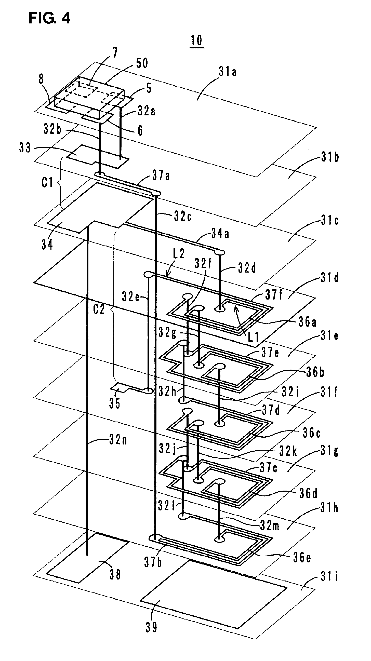
[0051]Hereinafter, preferred embodiments of an antenna and a radio IC device according to the present invention are described with reference to the drawings. In respective figures illustrating the respective preferred embodiments of the antenna and the radio IC device, common components and parts are denoted by the same reference numerals and redundant explanations are omitted.

Schematic Configuration of Antenna According to Preferred Embodiments of the Present Invention

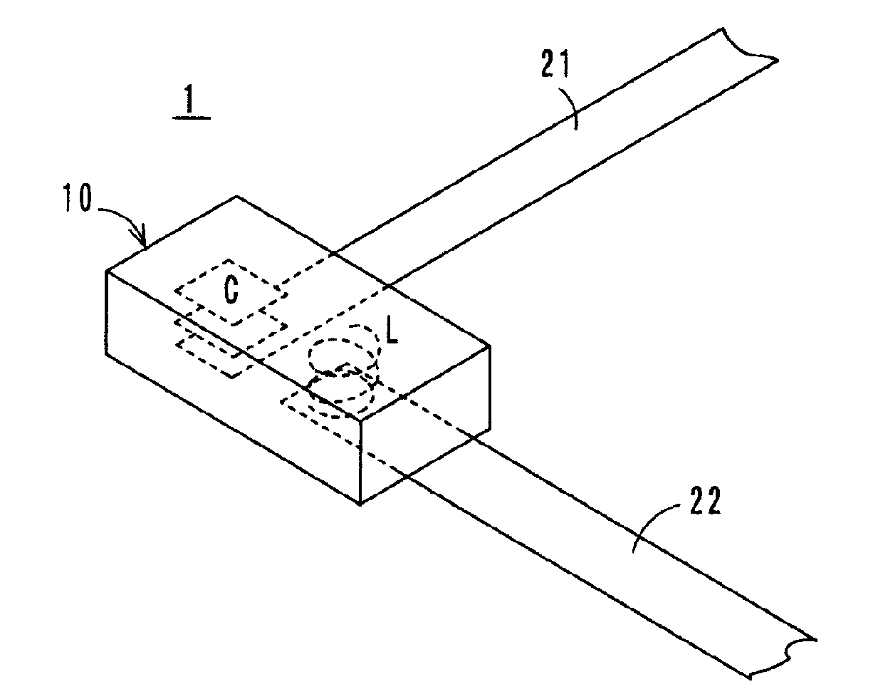
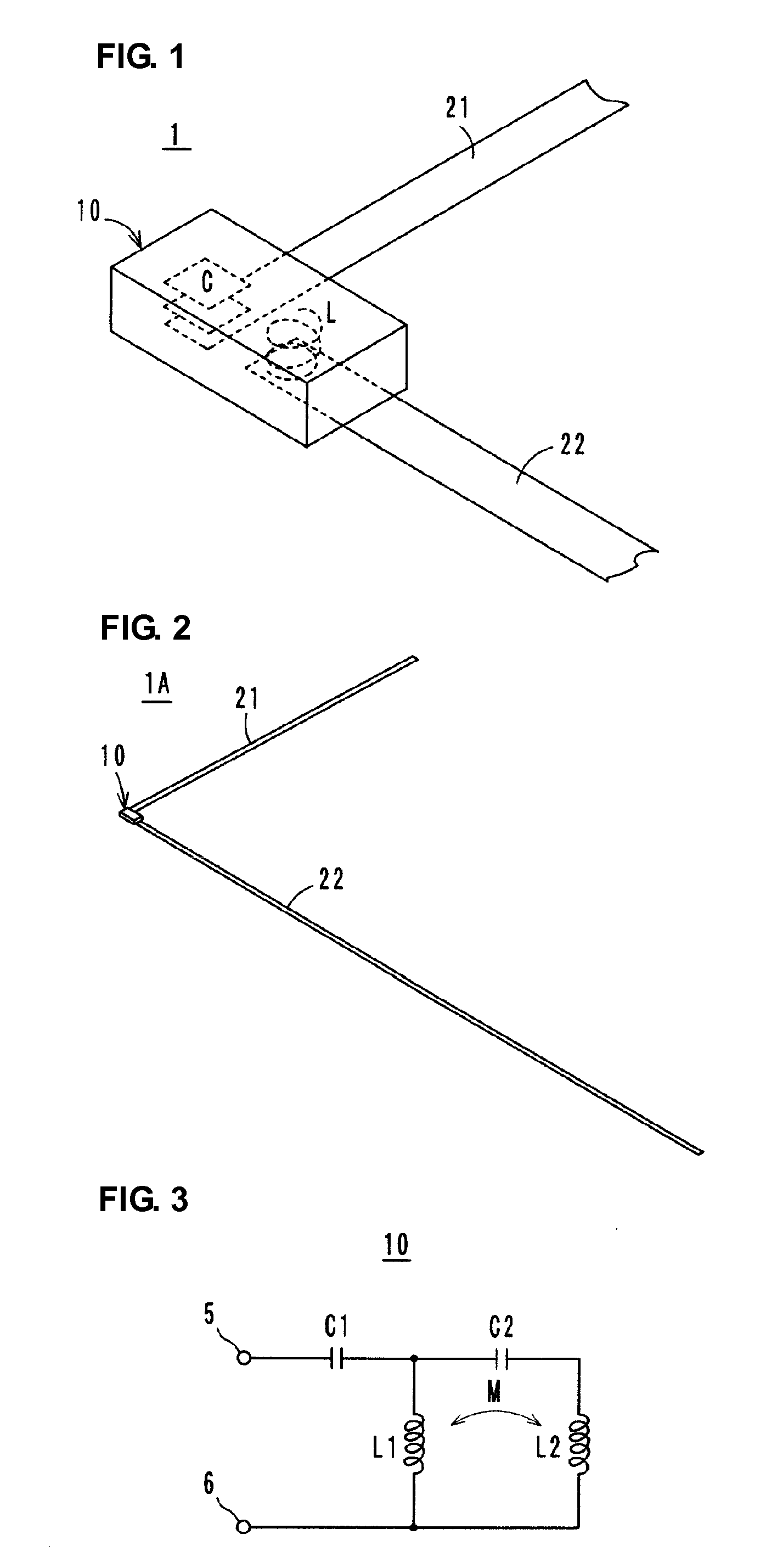
[0052]FIG. 1 schematically illustrates an antenna 1 according to preferred embodiments of the present invention. In the antenna 1, an antenna substrate 10 preferably includes a capacitance element C and an inductance element L defining an LC resonance circuit, the capacitance element C is arranged to be electromagnetically coupled to a first radiation plate 21, and the inductance element L is arranged to be electromagnetically coupled to a second radiation plate 22.

First Preferred Embodiment of Antenna

[0053]As illustr...


PUM


Abstract

An antenna includes a feeder terminal and a resonance circuit. The resonance circuit is defined by a capacitance element and an inductance element and includes first and second radiation plates. The capacitance element is electromagnetically coupled to the first radiation plate, and the inductance element is electromagnetically coupled to the second radiation plate. A radio IC device includes an electromagnetic coupling module including a feeder circuit substrate on which a radio IC chip is mounted, and radiation plates. The feeder circuit substrate includes an inductance element and a capacitance element. One of the radiation plates faces and is magnetically coupled to the inductance element. The other radiation plate faces and is electrically coupled to the capacitance element. The radio IC chip is operated by signals received by the radiation plates, and a response signal from the radio IC chip is radiated from the radiation plates.

Description

BACKGROUND OF THE INVENTION[0001]1. Field of the Invention[0002]The present invention relates to an antenna and a radio IC (Integrated Circuit) device, and particularly to an antenna capable of transmitting / receiving electromagnetic waves with a high gain and a radio IC device including a radio IC chip used for an RFID (Radio Frequency Identification) system.[0003]2. Description of the Related Art[0004]Generally, it is known that electromagnetic waves travel with an electric field component and a magnetic field component being substantially perpendicular to each other and that the energies of both components are substantially equivalent to each other. A conventional dipole antenna has been used for transmitting / receiving only an electric field component of electromagnetic waves, whereas a conventional loop antenna has been used for transmitting / receiving only a magnetic field component of electromagnetic waves. That is, conventional antennas have been used for transmitting / receiving...

Claims


Application Information

Patent Timeline
Patent Type & Authority Applications(United States)
IPC IPC(8): H01Q9/04H01Q1/24
CPCG06K7/10178G06K19/07749G06K19/07756G06K19/07779H01Q21/28G06K19/07784G06K19/07786H01Q1/2225G06K19/07783
Inventor DOKAI, YUYAKATO, NOBORU
Owner MURATA MFG CO LTD
Learn More