Fluid ejecting apparatus

a technology of ejecting apparatus and fluid, which is applied in the direction of printing, etc., can solve the problems of abnormal ejecting of ink, clogging of nozzles, and thickening of residual ink around the nozzles

Inactive Publication Date: 2009-04-30
SEIKO EPSON CORP
View PDF7 Cites 46 Cited by
  • Summary
  • Abstract
  • Description
  • Claims
  • Application Information

AI Technical Summary

Benefits of technology

[0023]With this configuration, it is possible to prevent the liqu

Problems solved by technology

In an ink jet recording apparatus that ejects ink onto a recording sheet through nozzles, residual ink may be thickened around the nozzles and the nozzles may become clogged.
Ink thickening or nozzle clogging causes ink to be abnormally ejected.
In this ink jet recording apparatus, when moisture is insufficiently supplied to the moisturizing cap device or when moisture supplied to the moisturizing cap device is insufficiently

Method used


Image

  • Fluid ejecting apparatus
  • Fluid ejecting apparatus
  • Fluid ejecting apparatus

Examples


first example

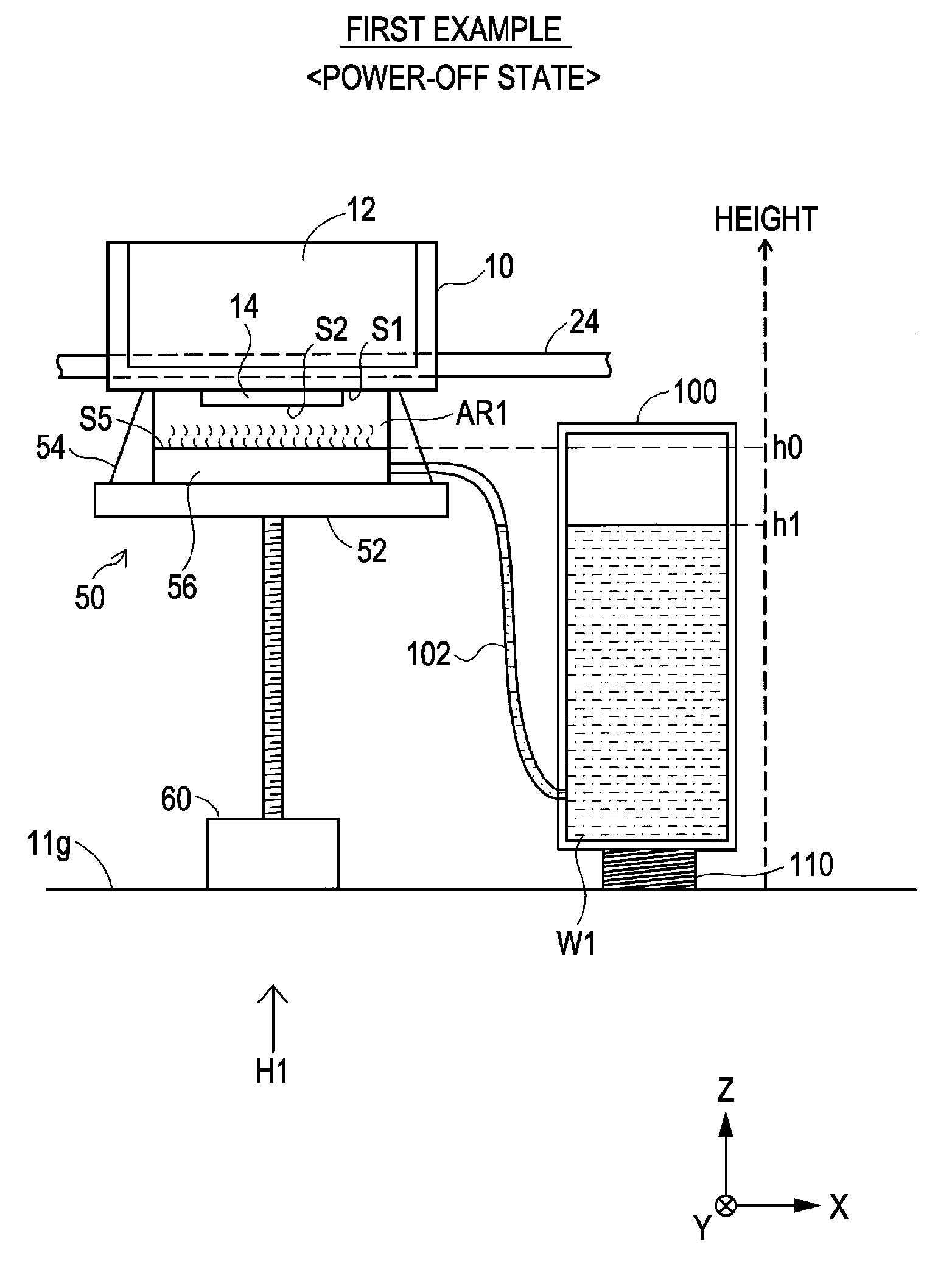
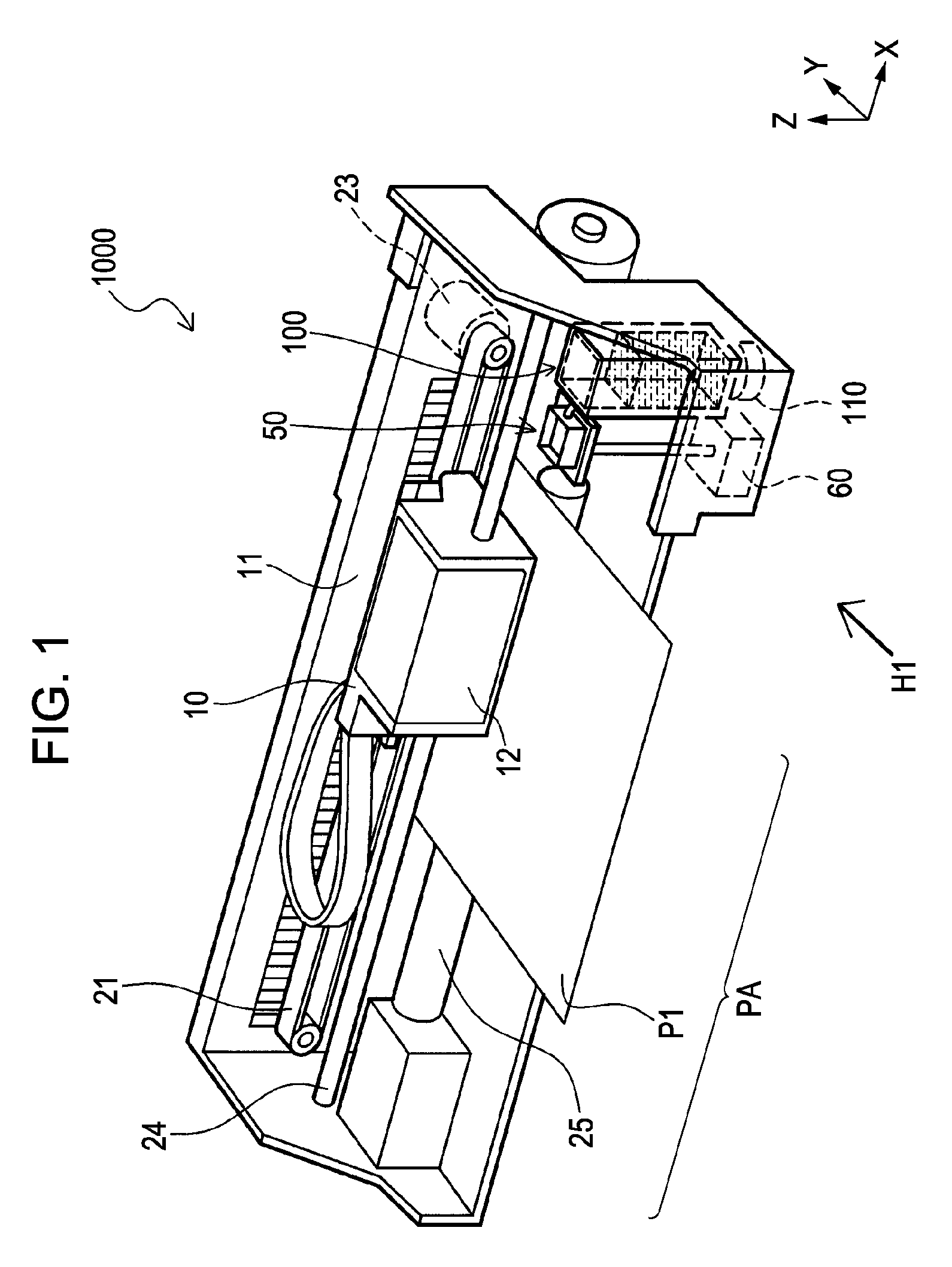
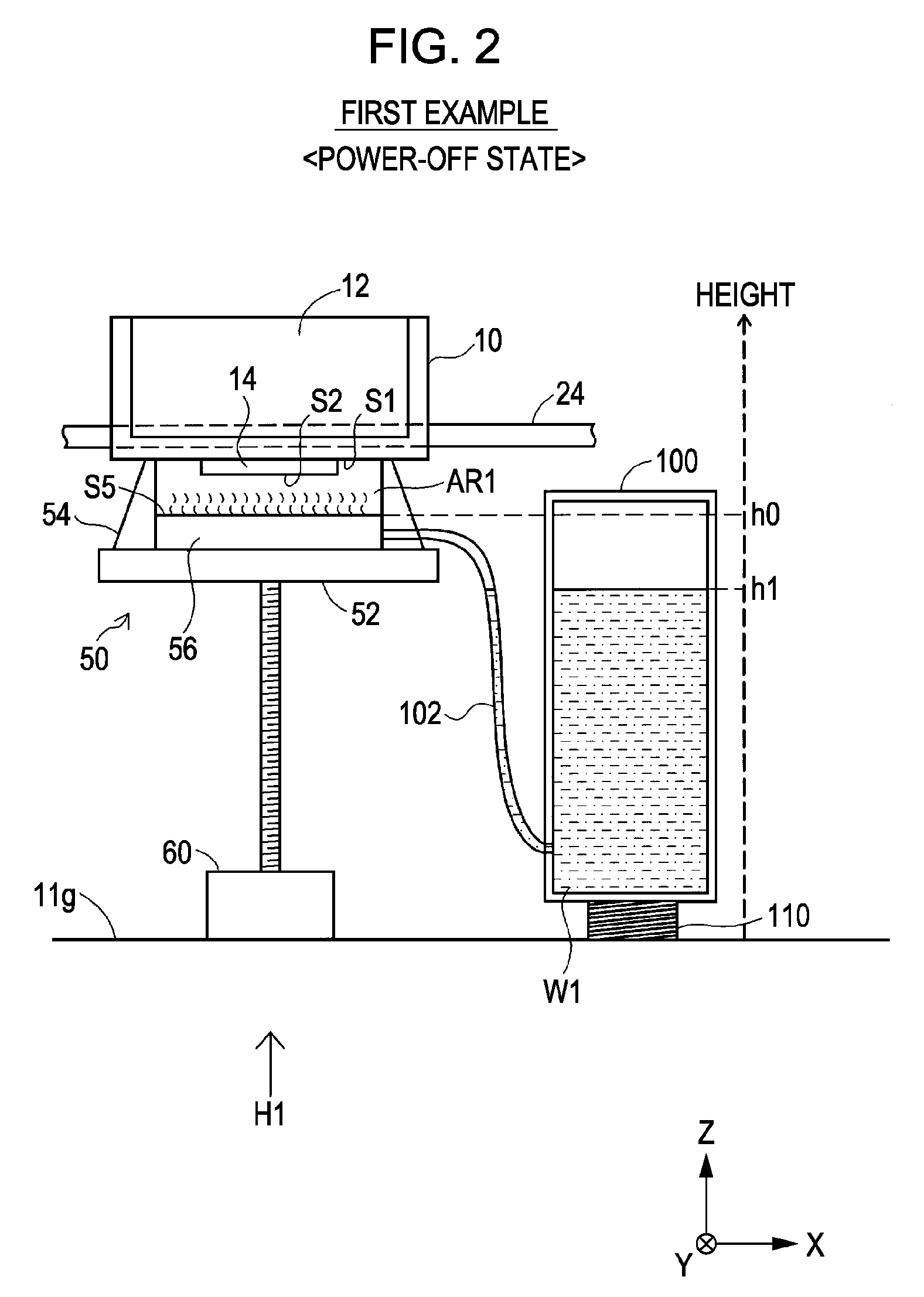
[0041]FIG. 1 is an explanatory view showing the schematic configuration of an ink jet printer as a fluid ejecting apparatus according to an example of the invention. A printer 1000 has a frame 11, and a platen 25 is arranged in the frame 11. A print sheet P1 is fed onto the platen 25 by a sheet feed mechanism (not shown). The printer 1000 also has a carriage 10. The carriage 10 is supported by a guide member 24 so as to be movable in a longitudinal direction (X-axis direction) of the platen 25, and reciprocates by means of a carriage motor 23 through a timing belt 21.

[0042]An ink cartridge 12 is mounted on the carriage 10. An ink jet recording head (hereinafter, simply referred to as “head”) (not shown) is attached at a lower part of the carriage 10. The carriage 10 is moved along the platen 25, and transports the head (not shown) so as to reciprocate on the print sheet P1. At this time, ink is ejected from the head (not shown), and thus printing is executed.

[0043]In the frame 11, a...

second example

[0054]FIG. 4 is an explanatory view showing the detailed configuration of a portion near a home position H1 in a power-off state according to a second example. A printer of the second example has a moisturizing cap device different from that of the printer 1000 (FIGS. 1 to 3). Other parts are the same as those in the first example.

[0055]Specifically, a moisturizing cap device 50a of the second example has no absorption member therein. The cap holder 52 is provided with a concave portion 57 at a portion facing the space surrounded by the cap portion 54. In the power-off state and the standby state, water serving as a moisturizing liquid, that is, water W2 is retained in the concave portion 57. The water W2 is evaporated in a substantially closed space AR2 surrounded by the bottom surface S1 of the head 14, the cap portion 54, and the cap holder 52 to humidify the head 14. At this time, a top surface of the concave portion 57 (a surface of the cap holder 52 facing the space AR2) is po...

third example

[0059]FIG. 6 is an explanatory view showing the detailed configuration of a portion near a home position H1 in a power-off state according to a third example. A printer of the third example is different from the printer 1000 (FIGS. 1 to 3) in that the height of the water head in the water tank is not constant. Other parts are the same as those in the first example.

[0060]Specifically, in the third example, a lift unit 150 having the same configuration as the moisturizing cap device lift unit 60, instead of the water tank lift unit 110 (FIG. 2) formed by a spring, is arranged below a water tank 100a as a lift unit. In the power-off state (standby state), the top surface S5 of the absorption member 56 in the moisturizing cap device 50 is positioned at a height h0 higher than a height h21 of the water W1 in the water tank 100a. Therefore, similarly to the first example, the water W1 is not supplied from the water tank 100a to the moisturizing cap device 50.

[0061]FIG. 7 is an explanatory...


PUM


Abstract

A fluid ejecting apparatus that ejects a fluid includes a head that ejects the fluid, a first moisturizing cap device that covers the head to moisturize the head, and a first moisturizing liquid supply portion that supplies, to the first moisturizing cap device, a first moisturizing liquid for moisturizing the head when the first moisturizing cap device covers the head. The first moisturizing liquid supply portion has a first tank that stores the first moisturizing liquid. The first moisturizing cap device has a first moisturizing liquid storage portion that stores the first moisturizing liquid to be supplied from the first moisturizing liquid supply portion. The first moisturizing liquid supply portion supplies the first moisturizing liquid stored in the first tank to the first moisturizing cap device in accordance with a water head difference between the first moisturizing liquid stored in the first tank and the first moisturizing liquid storage portion.

Description

CROSS-REFERENCE TO RELATED APPLICATIONS[0001]This application is based upon and claims the benefit of priority from prior Japanese Patent Applications No. 2007-276463, filed on Oct. 24, 2007, the entire contents of which are incorporated herein by reference.BACKGROUND[0002]1. Technical Field[0003]The present invention relates to a technology for resolving nozzle clogging in a fluid ejecting apparatus, which ejects a fluid.[0004]2. Related Art[0005]In an ink jet recording apparatus that ejects ink onto a recording sheet through nozzles, residual ink may be thickened around the nozzles and the nozzles may become clogged. Ink thickening or nozzle clogging causes ink to be abnormally ejected. To suppress ink thickening or nozzle clogging, an ink jet recording apparatus has been suggested in which, in a state where printing is not executed, a head is covered with a moisturizing cap device and moisture is supplied into a space of the moisturizing cap device to moisturize the head, thereby...

Claims


Application Information

Patent Timeline
IPC IPC(8): B41J2/165
CPCB41J2/16505B41J2/16552B41J2/16511
Inventor SHIMAZAKI, JUN
Owner SEIKO EPSON CORP
Why Eureka
Try Eureka