Higher fastening screw

a fastening screw and high-speed technology, applied in the field of screws, can solve problems such as the injuries of operators while screwing, and achieve the effect of reducing the screwing resistance and preventing the operator from hurting

Inactive Publication Date: 2009-04-30
ZYH YIN ENTERPRISE
View PDF7 Cites 8 Cited by
  • Summary
  • Abstract
  • Description
  • Claims
  • Application Information

AI Technical Summary

Benefits of technology

[0007]Therefore, the object of the present invention is to provide a screw comprising a plurality of concavities disposed on the threads for being sequentially connected as a state of a single helix, thereby assisting to thoroughly and sequentially sever fibers for reducing the screwing resistance and preventing from hurting the operators.
[0008]The screw in accordance with the present invention comprises a screw head, a shank, a drilling portion and a plurality of threads; wherein a plurality of concavities on the threads are sequentially connected to form a state of a single helix around the shank, started from a initial concavity located adjacent to the drilling portion and terminated at a final concavity located adjacent to the head. The initial concavity and the final concavity are positioned at relative places, thereby accurately aligning the above two concavities by an imaginary line. By means of the assistance of the concavities to cut and sever the fibers, the present invention is conducive to increase the screwing efficiency with less screwing resistance and also prevents from damaging the operators.

Problems solved by technology

In addition, the configuration of too many notches 221 on the threads 22 would also cause the problem of the injuries to the operators while screwing.

Method used


Image

  • Higher fastening screw
  • Higher fastening screw
  • Higher fastening screw

Examples


Embodiment Construction

[0018]Before the present invention is described in greater detail, it should be noted that the like elements are denoted by the same reference numerals throughout the disclosure.

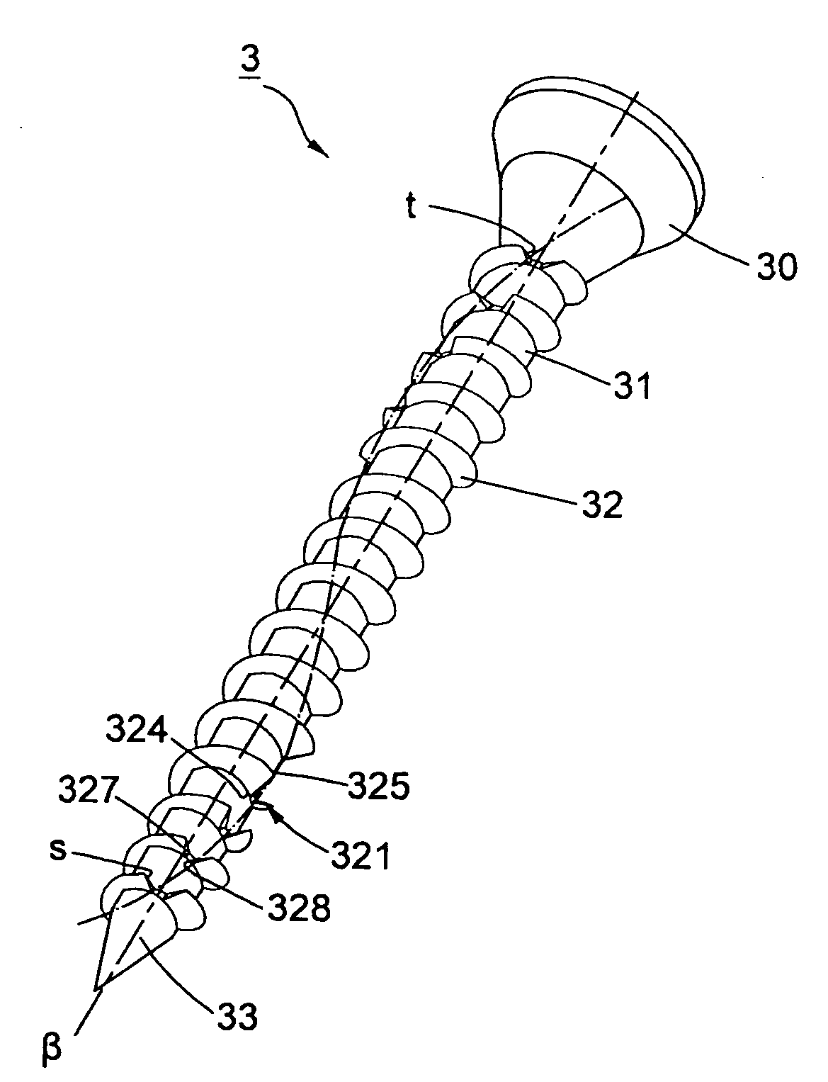
[0019]Referring to FIG. 4, a screw 3 of a first preferred embodiment comprises a screw head 30, a shank 31 longitudinally extending from the screw head 30, a drilling portion 33 disposed on the distal end of the shank 31, opposite to the screw head 30, and a plurality of threads 32 disposed on the shank 31; wherein each of threads 32 consists of a thread bottom 324 joined to the shank 31 and a thread crest 325 outwardly protruded from the shank 31. Further, a concavity 321 is defined by the inward curve of the thread crest 325 to form a bottom wall adjacent to the thread bottom 324 (shown in a second preferred embodiment of FIG. 6). It is adopted in the preferred embodiments of the present invention that the each of the concavities 321 has a thread crest 325 extremely curved toward the thread bottom 324 (sho...


PUM


Abstract

The present invention pertains to a higher fastening screw comprising a plurality of concavities formed on the threads, which are connected in sequence for being presented as a state of a single helix. Further, the concavities separately located adjacent to the screw head and to the drilling portion are disposed at relative positions for being accurately aligned by an imaginary line. In this manner, the configuration of the concavities would efficiently cut and sever the fibers of the object, so as to achieve a lower screwing resistance for a higher screwing efficiency and prevent the injuries to the operators.

Description

BACKGROUND OF THE INVENTION[0001]1. Field of the Invention[0002]The present invention relates to a screw, in particular a higher fastening screw.[0003]2. Description of the Related Art[0004]Referring to FIG. 1, a conventional screw 1 comprises a screw head 10, a shank 11 extending from the head 10 along a shank axis, a drilling portion 13 disposed at the distal end of the shank 11, and a plurality of threads 12 disposed on the shank 11; wherein each of the threads 12 provides with a notch 121 disposed around the outer edge thereof, and a plurality of the notches 121 are assumed to be sequentially joined by an imaginary line, started from an initial notch c located adjacent to the drilling portion 13 to a final notch d located adjacent to the screw head 10, which results in the line being inclined with respect to the shank axis by an angle.[0005]While screwing, the screw 1 is initially drilled into the object through the drilling portion 13 and the threads 12, and further the notches...

Claims


Application Information

Patent Timeline
Patent Type & Authority Applications(United States)
IPC IPC(8): F16B25/02
CPCF16B25/106F16B25/0052
Inventor CHEN, CHI-HSIANG
Owner ZYH YIN ENTERPRISE
Why Eureka
Try Eureka