Manipulator system and manipulator control method

a manipulator and manipulator technology, applied in the field of manipulator systems and manipulator control methods, can solve the problems of limited freedom of forceps, limited degree of freedom of available forceps, etc., and achieve the effect of high degree of freedom

Inactive Publication Date: 2009-04-30
KK TOSHIBA
View PDF3 Cites 383 Cited by
  • Summary
  • Abstract
  • Description
  • Claims
  • Application Information

AI Technical Summary

Benefits of technology

[0010]It is one of the objects of the present invention to provide a manipulator system and a manipulator control method, which have high d...

Problems solved by technology

The forceps that have been available heretofore, however, have few degrees of freedom, e.g., one degree of freedom, are difficult to handle because they are movable only in limited directions to grip and cut tissues and also to insert suture needles, and require surgeons to be skilled in using them.
However, external forces applied to the distal end working unit and gripping forces applied by the distal end working unit are not transmitted to the master side of the master-slave remote ...

Method used


Image

  • Manipulator system and manipulator control method
  • Manipulator system and manipulator control method
  • Manipulator system and manipulator control method

Examples


Embodiment Construction

[0026]Manipulator systems according to preferred embodiments of the present invention will be described below with reference to FIGS. 1 through 12.

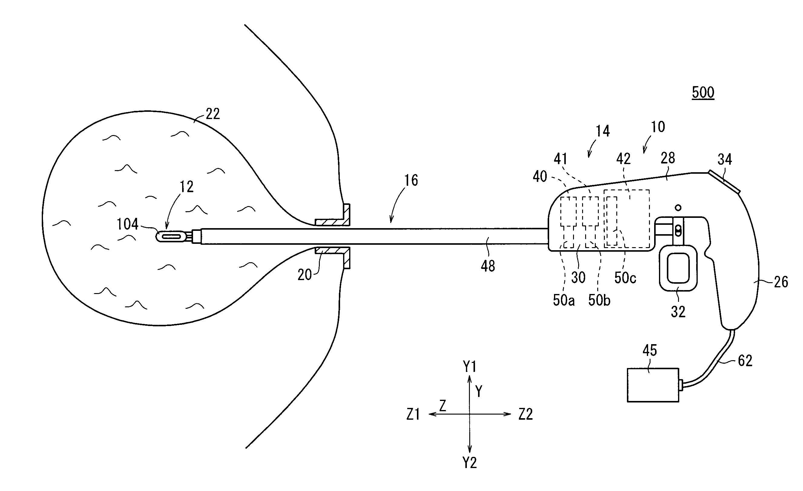
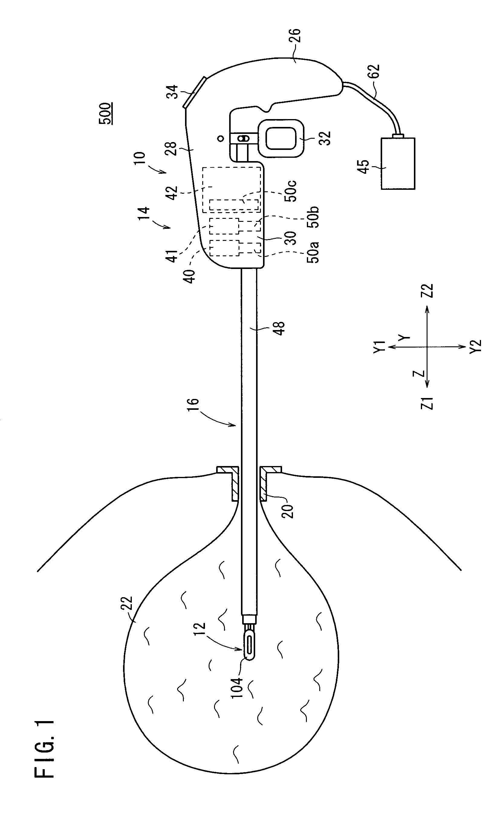
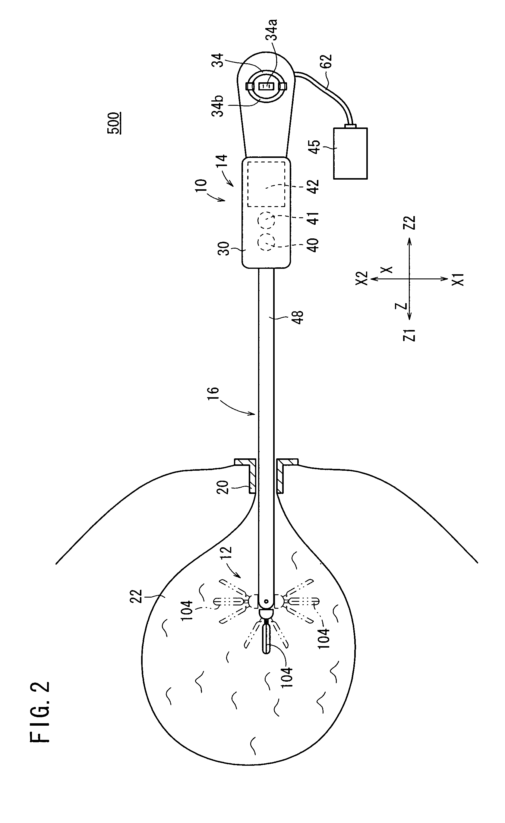
[0027]As shown in FIG. 1, a manipulator system 500 according to an embodiment of the present invention comprises a manipulator 10 and a controller 45 for controlling the manipulator 10.

[0028]The controller 45, which electrically controls the manipulator 10, is electrically connected to the manipulator 10 by a cable 62 extending from the lower end of a grip handle 26 of the manipulator 10. The controller 45 is capable of controlling a plurality of manipulators 10 independently at the same time as well as the single manipulator 10.

[0029]The manipulator 10 including an operating unit 14 and a working unit 16 will be described in detail below.

[0030]The manipulator 10 has a distal end working unit 12 for gripping a portion of a living tissue, a curved needle, or the like for performing a certain treatment, and is usually referred to as grippin...


PUM


Abstract

A manipulator has an operating unit including a trigger lever, a distal end working unit including an end effector and a yaw axis and a roll axis for changing the direction of the end effector, and a connector shaft interconnecting the operating unit and the distal end working unit. The operating unit includes an actuator block housing therein motors for actuating the yaw axis and the roll axis and a gripper operational quantity corrector for mechanically transmitting an operational action of the trigger lever to actuate the end effector. A controller calculates an interference amount caused on the end effector by the attitude angles of the yaw axis and the roll axis. The gripper operational quantity corrector is controlled by the controller to extend or retract a push rod, for correcting the operational quantity of the operational action of the trigger lever to compensate for the interference amount.

Description

BACKGROUND OF THE INVENTION[0001]1. Field of the Invention[0002]The present invention relates to a manipulator system and a manipulator control method, the manipulator system comprising a manipulator having a distal end working unit which includes an end effector axis and at least one attitude axis for changing the direction of the end effector axis, and a controller for controlling the manipulator. More particularly, the present invention relates to a manipulator system comprising a mechanism for operating the end effector axis and the attitude axis, and a manipulator control method.[0003]2. Description of the Related Art[0004]According to a laparoscopic surgical operation process, some small holes are opened in the abdominal region, for example, of a patient and a flexible scope and manipulators or forceps are inserted into the holes. The surgeon performs a surgical operation on the patient with the manipulators or forceps while watching an image captured by the flexible scope and...

Claims


Application Information

Patent Timeline
IPC IPC(8): B65G47/22G06F19/00A61B19/00B25J3/00
CPCA61B19/22A61B2019/2292A61B2017/2929A61B2017/00398A61B34/70A61B34/76
Inventor JINNO, MAKOTO
Owner KK TOSHIBA
Why Eureka
Try Eureka