Method of bone surgery

a bone surgery and bone technology, applied in the field of bone surgery, can solve the problems of loss of original bone shape, .e. shape, and achieve the effect of reducing the likelihood of damag

Inactive Publication Date: 2009-04-30
ROBERT GORDON UNIVERSITY
View PDF1 Cites 45 Cited by
  • Summary
  • Abstract
  • Description
  • Claims
  • Application Information

AI Technical Summary

Benefits of technology

[0025]More specifically, the method may comprise advancing the distal shaft portion of the first drill bit into the near cortex to an extent that the shoulder abuts against an exterior surface of the near cortex. Thus, the first drill bit may advance into the bone no further than a length of the distal shaft portion to thereby, for example, reduce the likelihood of damage to the far cortex if the first drill bit becomes over advanced.

Problems solved by technology

Upon healing of the fracture such a change in disposition can result in a loss of the original bone shape, i.e. the shape before the fracture.

Method used


Image

  • Method of bone surgery
  • Method of bone surgery
  • Method of bone surgery

Examples


Embodiment Construction

[0043]The advantages, and other features of the system disclosed herein, will become more readily apparent to those having ordinary skill in the art from the following detailed description of certain preferred embodiments taken in conjunction with the drawings which set forth some representative embodiments of the present invention. The apparatus used in the present disclosure will be described before the method of the disclosure is described.

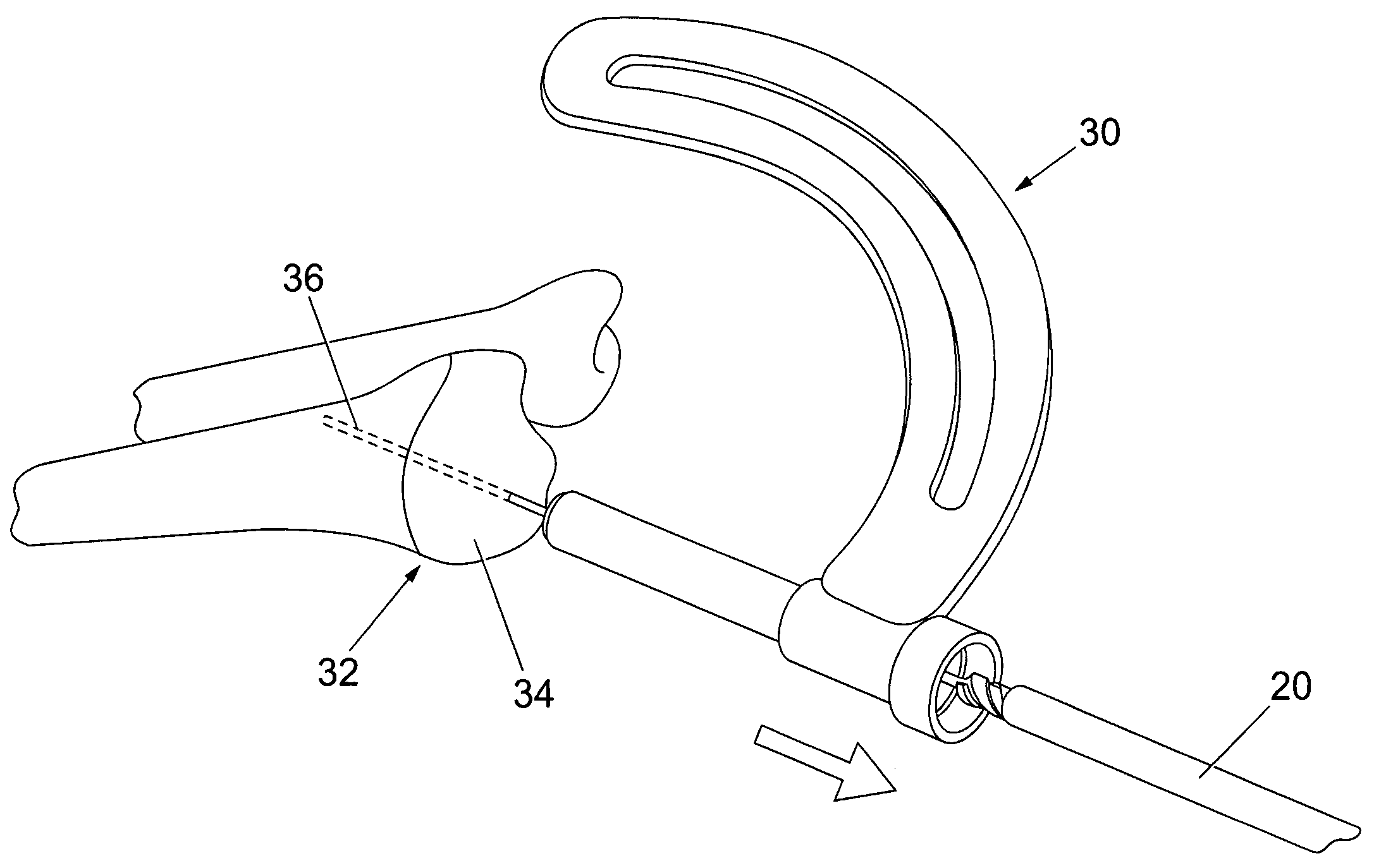
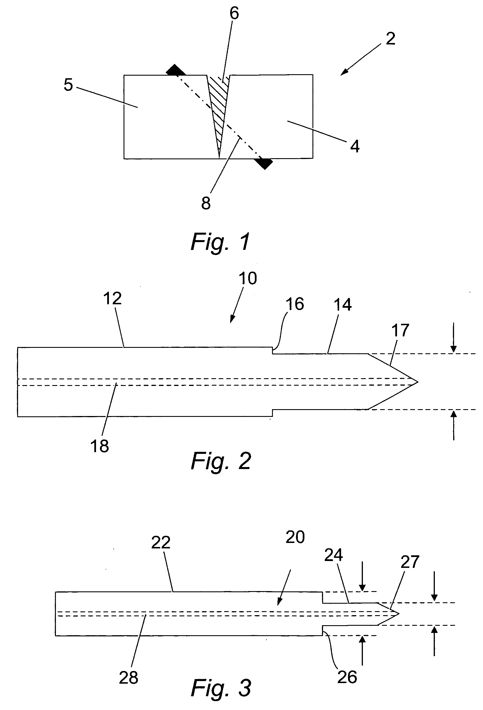
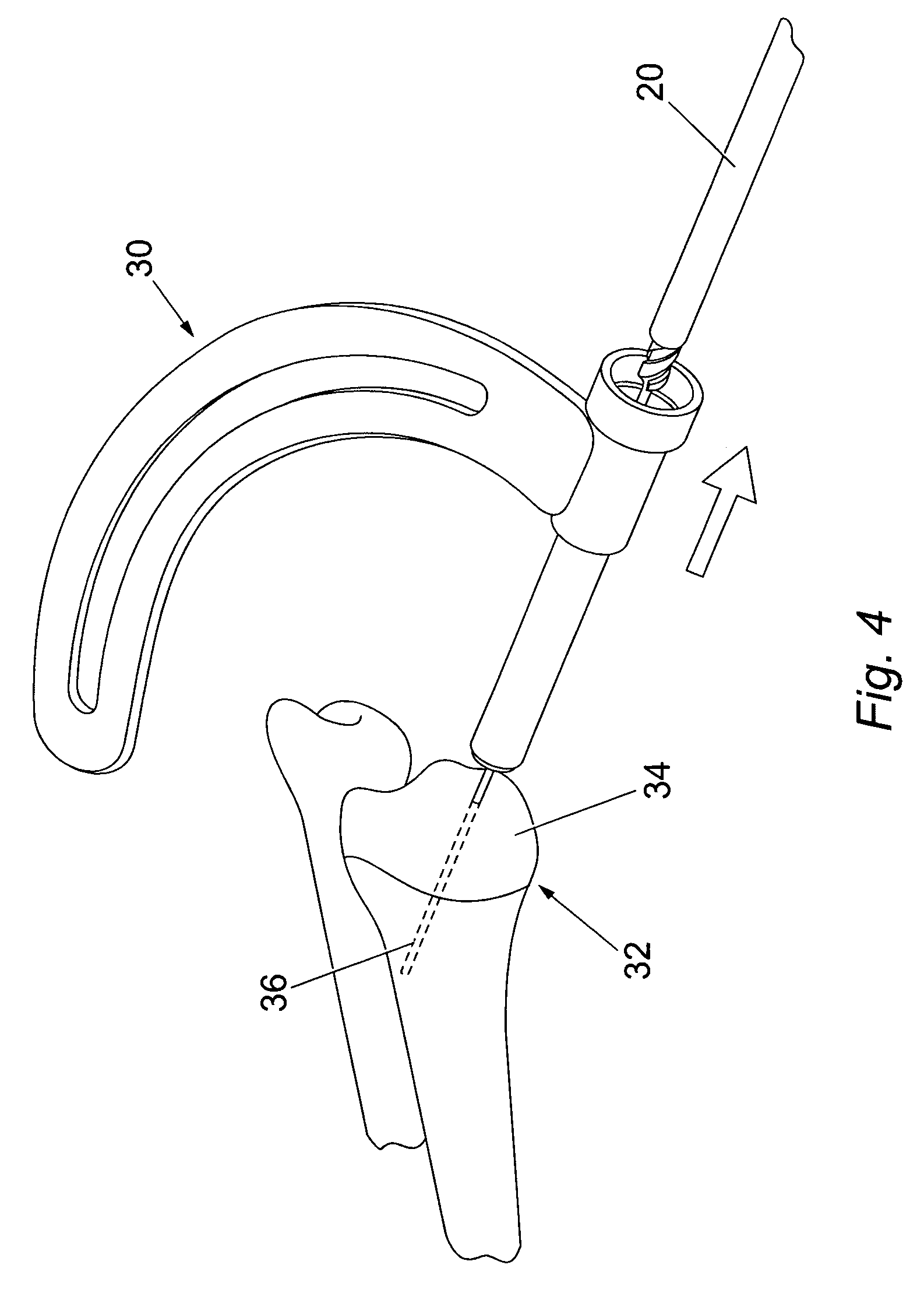
[0044]As described above, a fractured bone 2 may have the form shown in FIG. 1, in which two bone portions 4, 5 define a fracture 6 between them. Muscles and ligaments around the bone can cause the bone portions 4, 5 to be placed under compression or extension causing the relative disposition of the bone portions to change. Upon healing of the fracture such a change in disposition can result in a loss of the original bone shape. According to the method of the present disclosure, bores are drilled in the bone portions 4, 5 to receive and engage ...


PUM


Abstract

A method of bone surgery including drilling a first bore in a near cortex of the bone with a first drill bit. Then a second drill bit is passed though the first bore towards a far cortex of the bone, the second drill bit comprising a distal shaft portion and a proximal shaft portion, the distal shaft portion having a diameter less than a diameter of the proximal shaft portion such that a shoulder is defined between the distal and proximal shaft portions. Then a second bore is drilled in the far cortex of the bone with the distal shaft portion of the second drill bit whilst the second drill bit is received in the first bore.

Description

CROSS-REFERENCE TO RELATED APPLICATION[0001]This application claims priority to U.K. Patent Application No. 0705617.9, filed Mar. 23, 2007, which is incorporated herein by reference.FIELD OF THE INVENTION[0002]The present invention relates to a method of bone surgery.BACKGROUND TO THE INVENTION[0003]A fractured bone may have a form in which two bone portions define a fracture between them. Muscles and ligaments around the bone can cause the bone portions to be placed under compression or extension causing the relative disposition of the bone portions to change. Upon healing of the fracture such a change in disposition can result in a loss of the original bone shape, i.e. the shape before the fracture. Accordingly, it is known to hold the bone portions in relation to each other by means of a bone screw, which compresses the fractured bone portions. The bone screw maintains the bone portions in a desired relative disposition until the fracture heals and thereby reduces the likelihood ...

Claims


Application Information

Patent Timeline
Patent Type & Authority Applications(United States)
IPC IPC(8): A61B17/00A61B19/00A61B17/58
CPCA61B17/1615A61B2017/564A61B17/8645A61B17/8625
Inventor JOHNSTONE, ALAN J.
Owner ROBERT GORDON UNIVERSITY
Why Eureka
Try Eureka