Machine and Method for Packaging Groups of Products

a technology of machine and product, applied in the field of packaging products, can solve the problems of limited device efficiency, limited production rate, and low efficiency of plant layout, and achieve the effect of reducing high cost and increasing the control flexibility of orienting conveyors

Inactive Publication Date: 2009-05-07
KPL PACKAGING
View PDF11 Cites 8 Cited by
  • Summary
  • Abstract
  • Description
  • Claims
  • Application Information

AI Technical Summary

Benefits of technology

[0035]In a possible embodiment, the conveyor elements are driven around drive pulleys of proportionally different diameters keyed onto at least one motor shaft made to rotate, for example, by an independent motor. It would also be possible for motion to be obtained from a motor of a different section of the line. Alternatively, each conveyor element could be provided with its own motor, in which case the single conveyor elements do not require to be driven around pulleys with proportionally different diameters, as the difference in speed can be imposed by acting on the electronic controls of the motors. It would also be possible to provide mixed solutions, where two or more motors control the rotation of two or more groups of pulleys on which corresponding conveyor elements are driven. For example, two aligned motor driven shafts, each equipped with a plurality of pulleys of proportionally different diameters, could be provided. The use of two motors eliminates the high costs of providing a motor for each flexible conveyor element while increasing the control flexibility of the orienting conveyor, for example, also to correct any angular positioning errors.

Problems solved by technology

The need to deviate the feed path of the groups of products by 90° causes drawbacks in terms of plant layout.
Besides the drawbacks deriving from the overall dimensions of the packaging line in the plane, caused by the deviation of 90° in the feed path of the groups of products, a further drawback of conventional packaging lines is the limited efficiency of the devices that perform the 90° deviation in the path of the groups of products and consequently a limitation in the production rates that can be reached.
Moreover, the semi-finished pack is subjected to sudden changes in direction which can compromise the quality of the result of the process and determine a physical limitation in the possibilities of increasing the products speed of current machines.

Method used


Image

  • Machine and Method for Packaging Groups of Products
  • Machine and Method for Packaging Groups of Products
  • Machine and Method for Packaging Groups of Products

Examples


first modified embodiment

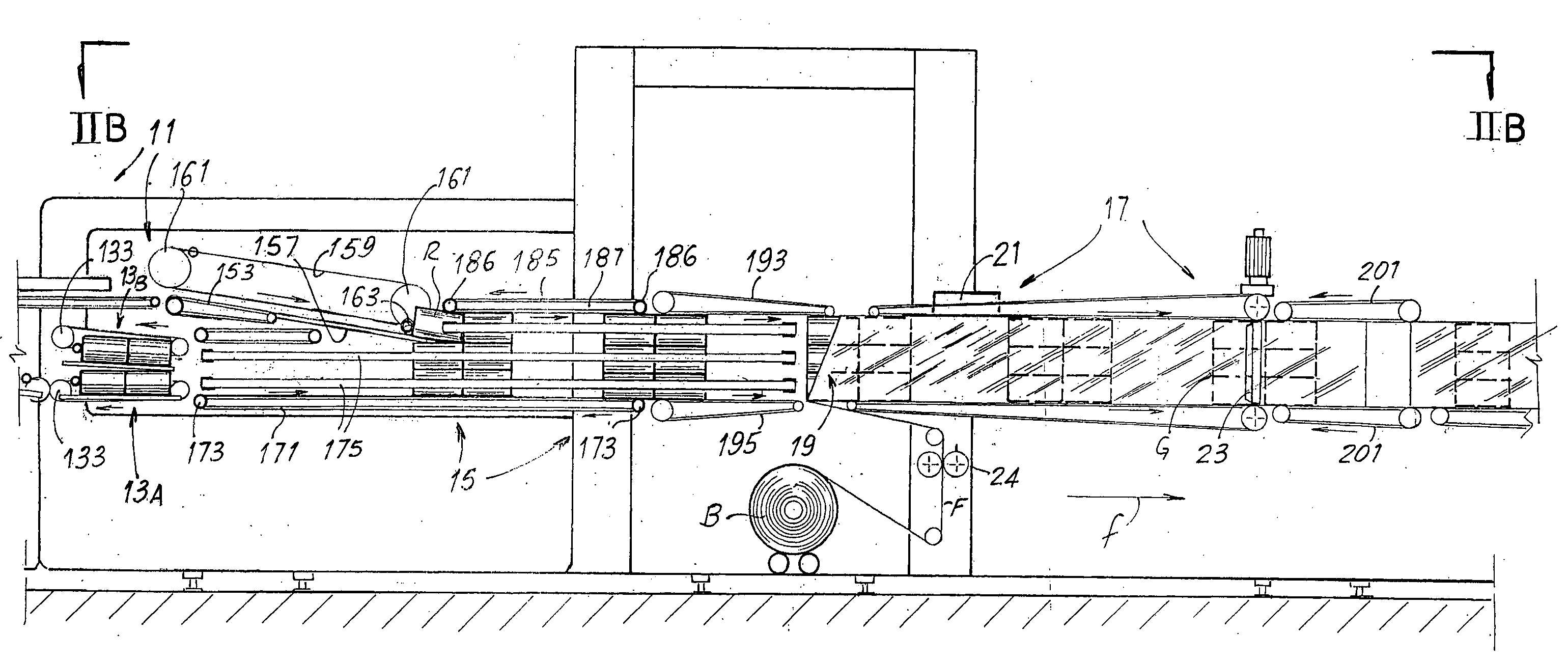
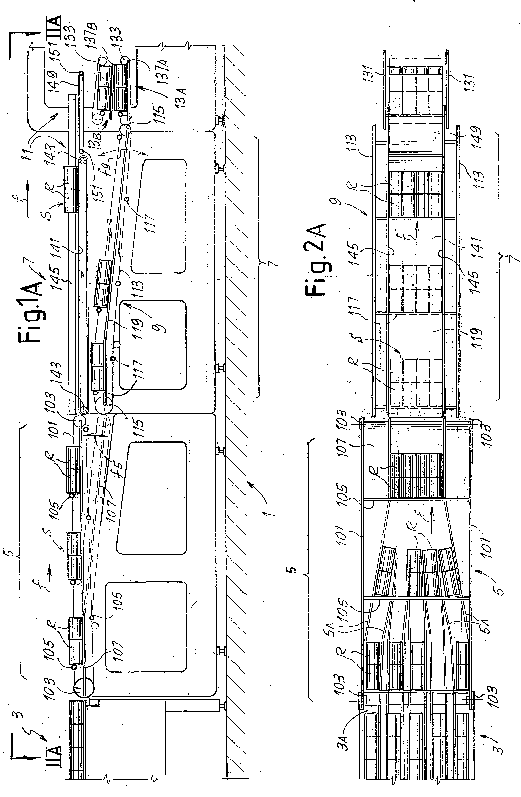
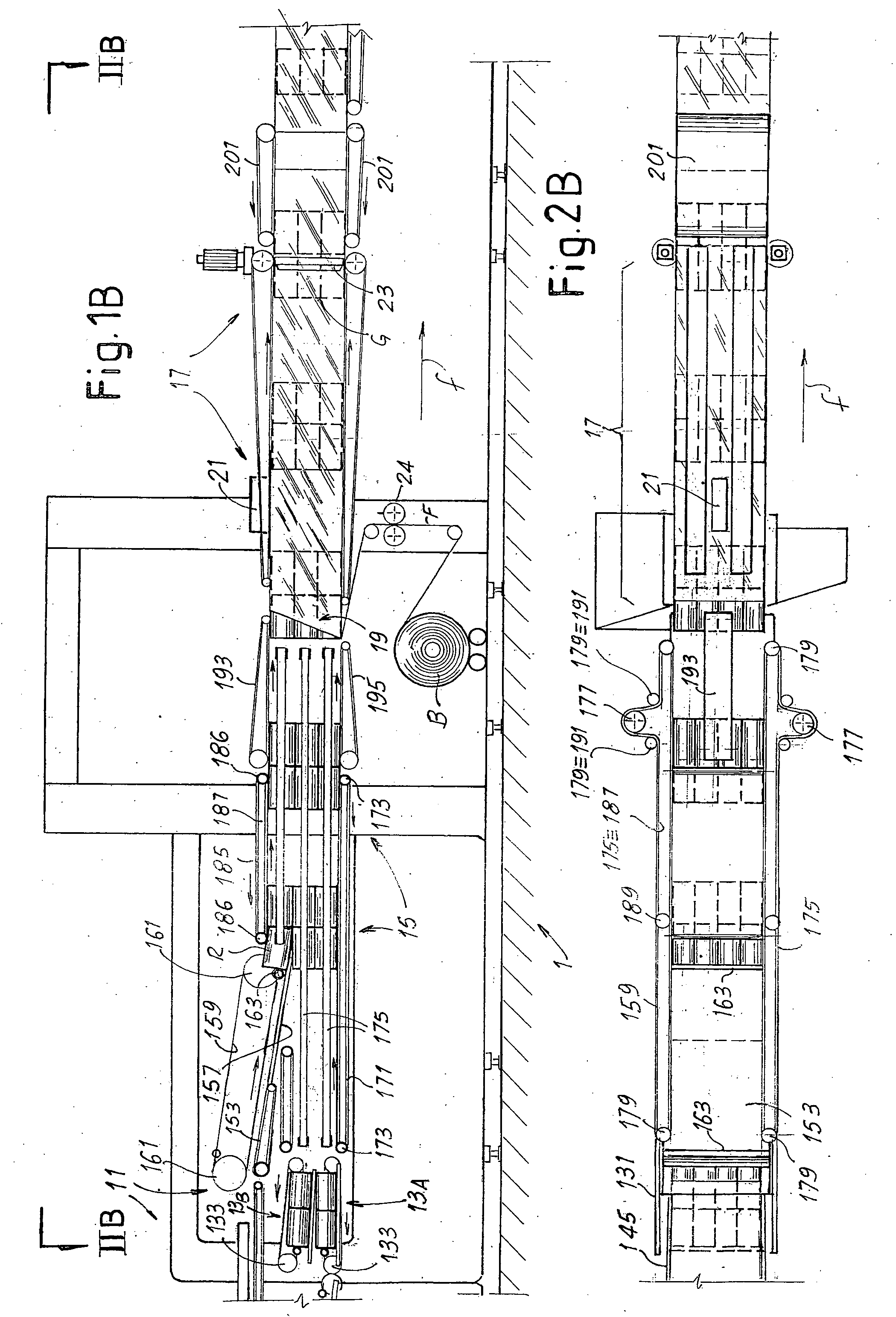
[0096]It must be understood that the corrector device 27 can also take different configurations with respect to that illustrated. For example, in a first modified embodiment, the upper conveyor belts 231 could be removed.

second modified embodiment (see fig.4)

[0097]In a second modified embodiment (see FIG. 4) the corrector device 27 can comprise a continuous flexible member 251, for example formed by a pair of belts disposed on two parallel vertical planes, which carry one or more pushers in the form of blades 253. The arrangement is such that the blades 253 follow a closed path P1 along which a first section is identified parallel to a sliding surface 255, along which the blades 253 advance in the same direction as the direction f of feed of the products, and a second return section. This arrangement allows any angular errors to be corrected, as the push exerted by the blades 253 on the groups G of products R forces them to take a position with the face thereof in contact with the blades 253 parallel thereto, and the blades will be constrained to lie in a vertical plane orthogonal to the direction f of feed of the groups G of products. Correction of transverse positioning errors can for example take place by supplying a portion of the s...


PUM

PropertyMeasurementUnit
lengthaaaaaaaaaa
speedsaaaaaaaaaa
lengthsaaaaaaaaaa

Abstract

To orient groups of products to be packaged in a plastic film the groups (G) are wrapped in lengths of film and fed between two series of opposite conveyor belts (211, 212). Each series of belts comprises several parallel belts controlled at proportionally variable speeds to cause the group (G) to rotate through approximately 90° about an axis orthogonal to the direction of feed.

Description

TECHNICAL FIELD[0001]The present invention relates to improvements to methods and machines for packaging products ordered according to superposed layers.[0002]More specifically, although not exclusively, the invention relates to methods and machines for packaging rolls of tissue paper, such as toilet paper, kitchen paper or the like.STATE OF THE ART[0003]In the packaging industry there are frequently produced packs of products assembled in ordered groups and contained inside a wrapping made of plastic film. This technique is typically used to package rolls of tissue paper, such as toilet paper, kitchen paper or the like.[0004]Normally, particularly when producing packs of rolls of tissue paper, single layers of product are fed according to a direction of feed and a plurality of layers are superposed to form a group of ordered products. This group of superposed layers is then introduced into a plastic film suitably shaped in the form of a tube by means of a forming collar or the like...

Claims


Application Information

Patent Timeline
Patent Type & Authority Applications(United States)
IPC IPC(8): B65B35/36B65B35/20B65B1/30B65B9/067
CPCB65B9/067B65B25/146B65B35/44B65B35/52B65G57/32B65B61/04B65G47/2445B65G47/31B65B35/58
Inventor GIULIANI, NICOLA
Owner KPL PACKAGING
Why Eureka
Try Eureka