Dual band helical antenna with wide bandwidth

a helical antenna and wide bandwidth technology, applied in the direction of simultaneous aerial operations, antenna details, antennas, etc., can solve the problems of not necessarily providing on a helical antenna with fixed coil pitch angle, coil diameter, coil turn number and spacing, etc., to increase high frequency bandwidth, wide bandwidth, and wide bandwidth

Inactive Publication Date: 2009-05-07
MITAC TECH CORP
View PDF11 Cites 4 Cited by
  • Summary
  • Abstract
  • Description
  • Claims
  • Application Information

AI Technical Summary

Benefits of technology

[0007]A primary object of the present invention is to provide a dual band helical antenna, which includes a first antenna section having an expanded diameter larger than that for the conventional dual band helical antennas and therefore has an increased high frequency bandwidth.
[0009]The dual band helical antenna according to the present invention includes a diametrically expanded antenna section having an expanded diameter and therefore has largely increased high frequency bandwidth, compared to the conventional dual band helical antennas, allowing the dual band helical antenna to be applied in more different bandwidths. In addition to a substantially zero-spacing dense coil, the diametrically expanded antenna section may be otherwise manufactured using a metal braided net or an elastic flexible metal tube, so as to overcome the difficulties in manufacturing the highly dense coil and to lower the labor and manufacturing costs for the dual band helical antenna.

Problems solved by technology

According to the currently available techniques for helical antenna, it is not necessarily to provide on a helical antenna with fixed coil pitch angle, coil diameter, and number and spacing of coil turns.
However, there is still space for improving the second conventional dual band helical antenna 200.

Method used


Image

  • Dual band helical antenna with wide bandwidth
  • Dual band helical antenna with wide bandwidth
  • Dual band helical antenna with wide bandwidth

Examples


Embodiment Construction

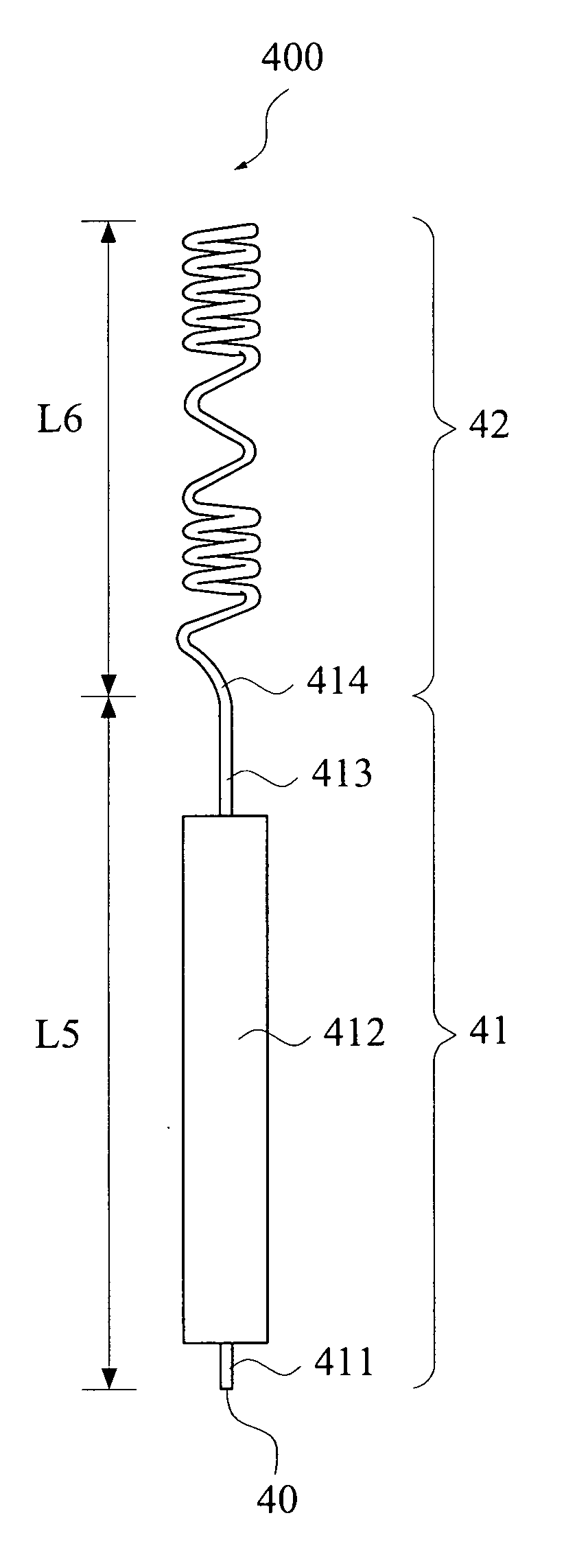
[0016]Please refer to FIG. 3 that is a side view of a dual band helical antenna 300 according to a first embodiment of the present invention. As shown, the dual band helical antenna 300 includes a signal feed point 30, a straight section 31, and a helical tail section 32. The signal feed point 30 is located at a lower end of the straight section 31 and is connected to a signal source for feeding in an antenna signal. The straight section 31 includes an impedance matching section 311, a diametrically expanded section 312, a transit section 313, and a junction 314, and has a first coil length L5, which determines a high-frequency resonant frequency of the dual band helical antenna 300. The impedance matching section 311 includes a length of relatively sparse coil. However, the sparseness of the coil of the impedance matching section 311 may be adjusted to change an equivalent inductance value of the impedance matching section 311, so as to achieve impedance matching for the dual band ...


PUM


Abstract

A dual band helical antenna with wide bandwidth includes a straight section and a helical tail section having a first and a second coil length, respectively. The straight section has a signal feed point located at a lower end thereof being connected to a signal source for feeding in an antenna signal. The first coil length determines a high-frequency resonant frequency of the dual band helical antenna, and a total length of the first and the second coil length determines a low-frequency resonant frequency of the dual band helical antenna. The straight section includes a diametrically expanded section to increase a high-frequency bandwidth of the dual band helical antenna.

Description

FIELD OF THE INVENTION[0001]The present invention relates to a dual band helical antenna, and more particularly to a dual band helical antenna with increased high-frequency bandwidth.BACKGROUND OF THE INVENTION[0002]In the conventional antenna techniques, a helical antenna is frequently used as a signal transmitting and receiving device. Compared to the general cylindrical antenna, the helical antenna has the advantage of having an antenna length shorter than that of a monopole antenna, and is therefore widely adopted among users. According to the currently available techniques for helical antenna, it is not necessarily to provide on a helical antenna with fixed coil pitch angle, coil diameter, and number and spacing of coil turns. Therefore, two or more sections having different lengths may be provided on the helical antenna for use with different resonant frequencies, so as to achieve the function of dual-frequency or multi-frequency for application in the GSM 900 / 1800 MHZ system ...

Claims


Application Information

Patent Timeline
Patent Type & Authority Applications(United States)
IPC IPC(8): H01Q1/36H01Q5/364
CPCH01Q5/364H01Q1/362
Inventor CHUNG, SHYH-JONGWANG, YU-HSINCHENG, YU-CHIANG
Owner MITAC TECH CORP
Why Eureka
Try Eureka