
End plates for fuel cell stack and method of manufacturing the same

Inactive Publication Date: 2009-05-07
HYUNDAI MOTOR CO LTD
View PDF4 Cites 5 Cited by
  • Summary
  • Abstract
  • Description
  • Claims
  • Application Information

AI Technical Summary

Benefits of technology

[0020]Accordingly, the present invention has been made in an effort to solve the above-described drawbacks, and one of the objects of the present invention is to provide an end plate for a fuel cell stack and a method of manufacturing the same, in which the end plate to be connected to each of both ends of a fuel cell stack are manufactured in a hybrid structure using a composite base material and a plurality of steel reinforced materials having different coefficients of thermal expansion such that a bent deformation caused by the different coefficients of thermal expansion and an elastic deformation caused by the clamping force are cancelled by each other, thus maintaining a flat surface state.
[0021]In one aspect, the present invention provides an end plate for a fuel cell stack having a hybrid structure comprising a base material and a plurality of reinforced materials having different coefficients of thermal expansion such that a bent is formed in the end plate before being connected to a fuel cell stack and the bent is deformed into a flat surface after being connected to the fuel cell stack.
[0022]In a preferred embodiment, the base material is a composite base material and the reinforced materials are steel reinforced materials, the plurality of steel reinforced materials being provided inside the composite base material at regular intervals in the longitudinal direction of

Problems solved by technology

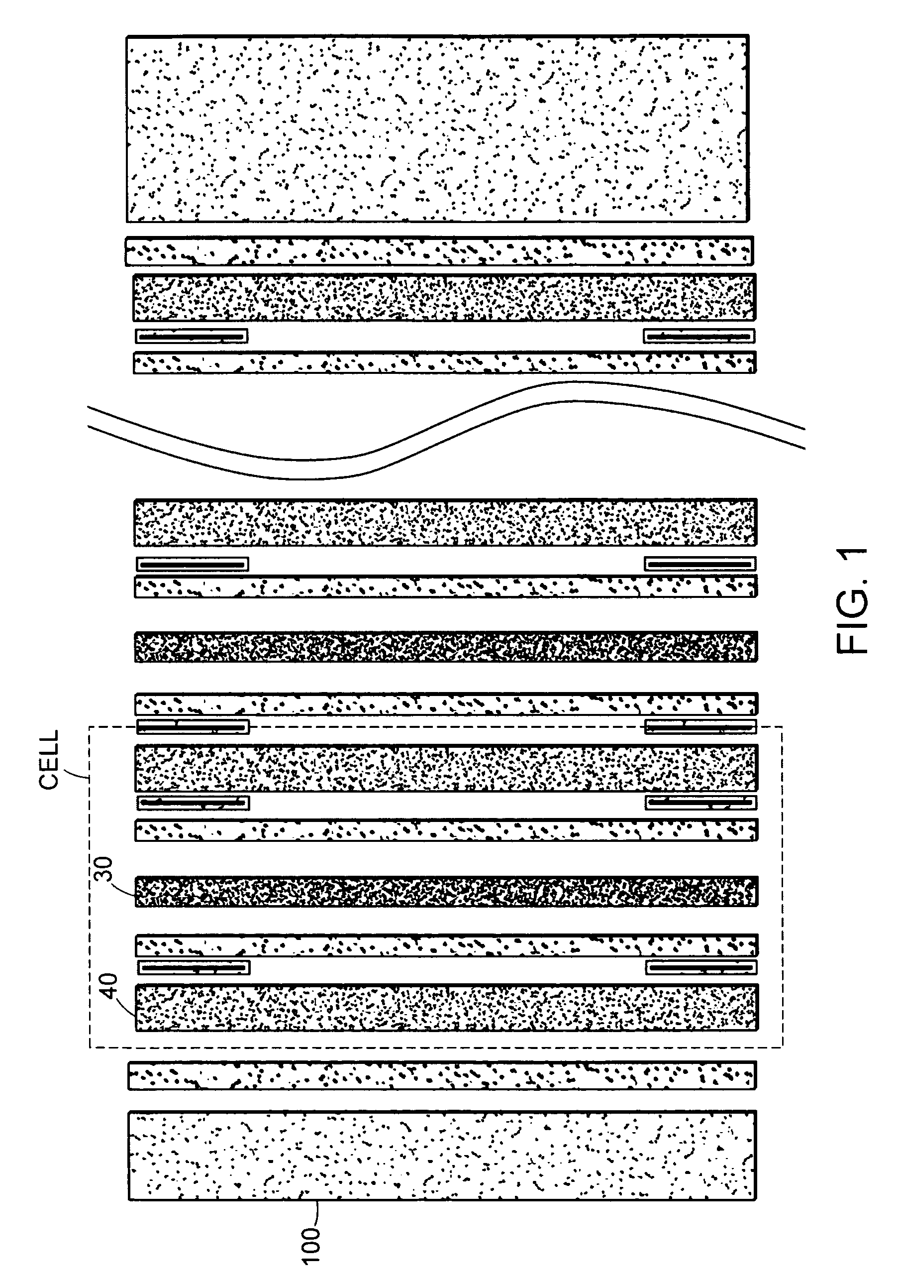
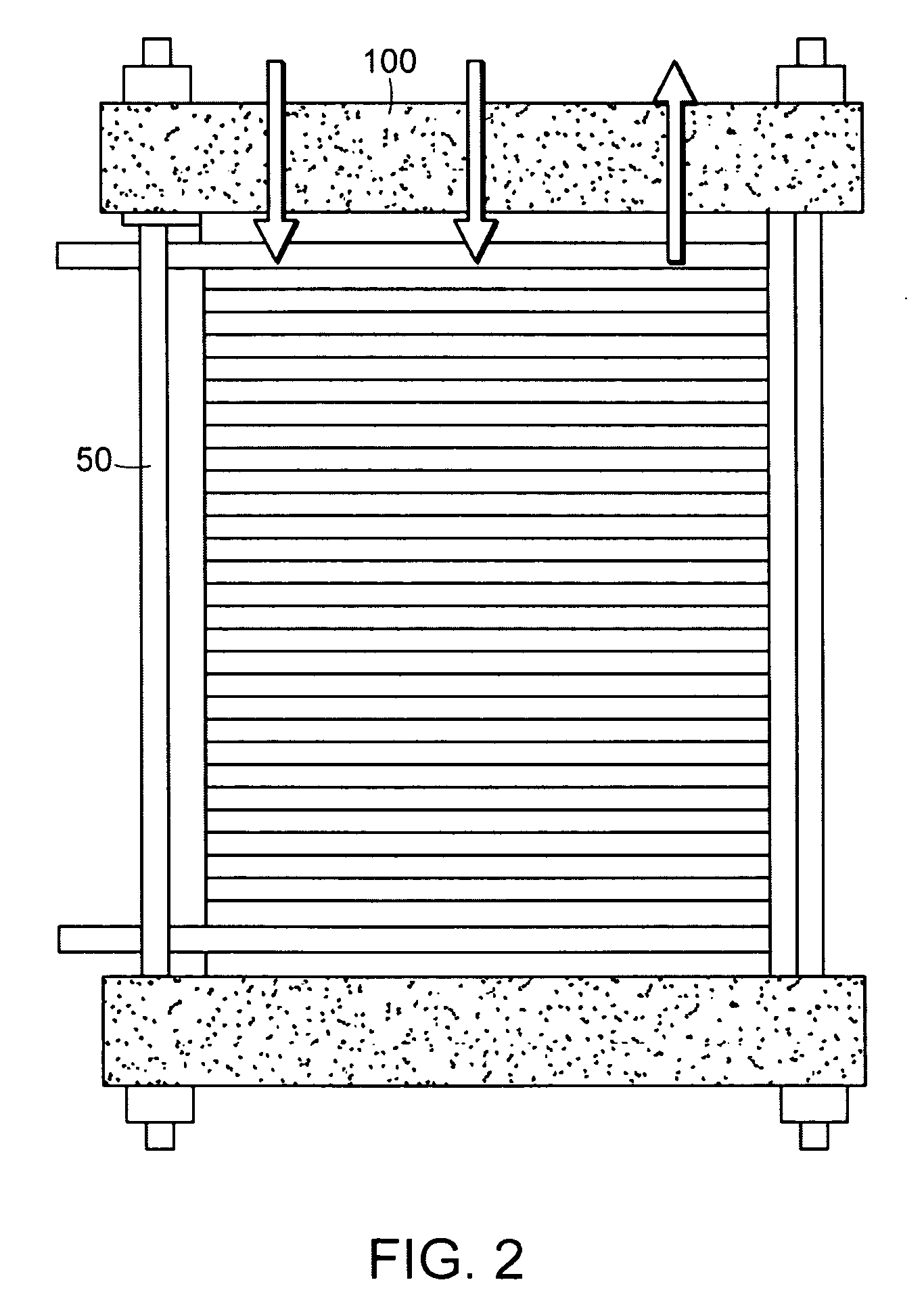
However, the conventional methods of connecting the end plates have the following drawbacks.
When the middle portion of the end plate gets loose, electrical contact resistance may be increased in the middle portion of the fuel cell stack, to which a lower surface pressure is applied, and fluid leakage may occur.
However, such a method has drawbacks in that the NC machining process requires high cost and it is very difficult to process the curved surface to fit the deformation region of the end plate.

Method used


Image

  • End plates for fuel cell stack and method of manufacturing the same
  • End plates for fuel cell stack and method of manufacturing the same
  • End plates for fuel cell stack and method of manufacturing the same

Examples


Embodiment Construction

[0034]Reference will now be made in detail to the preferred embodiment of the present invention, examples of which are illustrated in the drawings attached hereinafter, wherein like reference numerals refer to like elements throughout. The embodiments are described below so as to explain the present invention by referring to the figures.

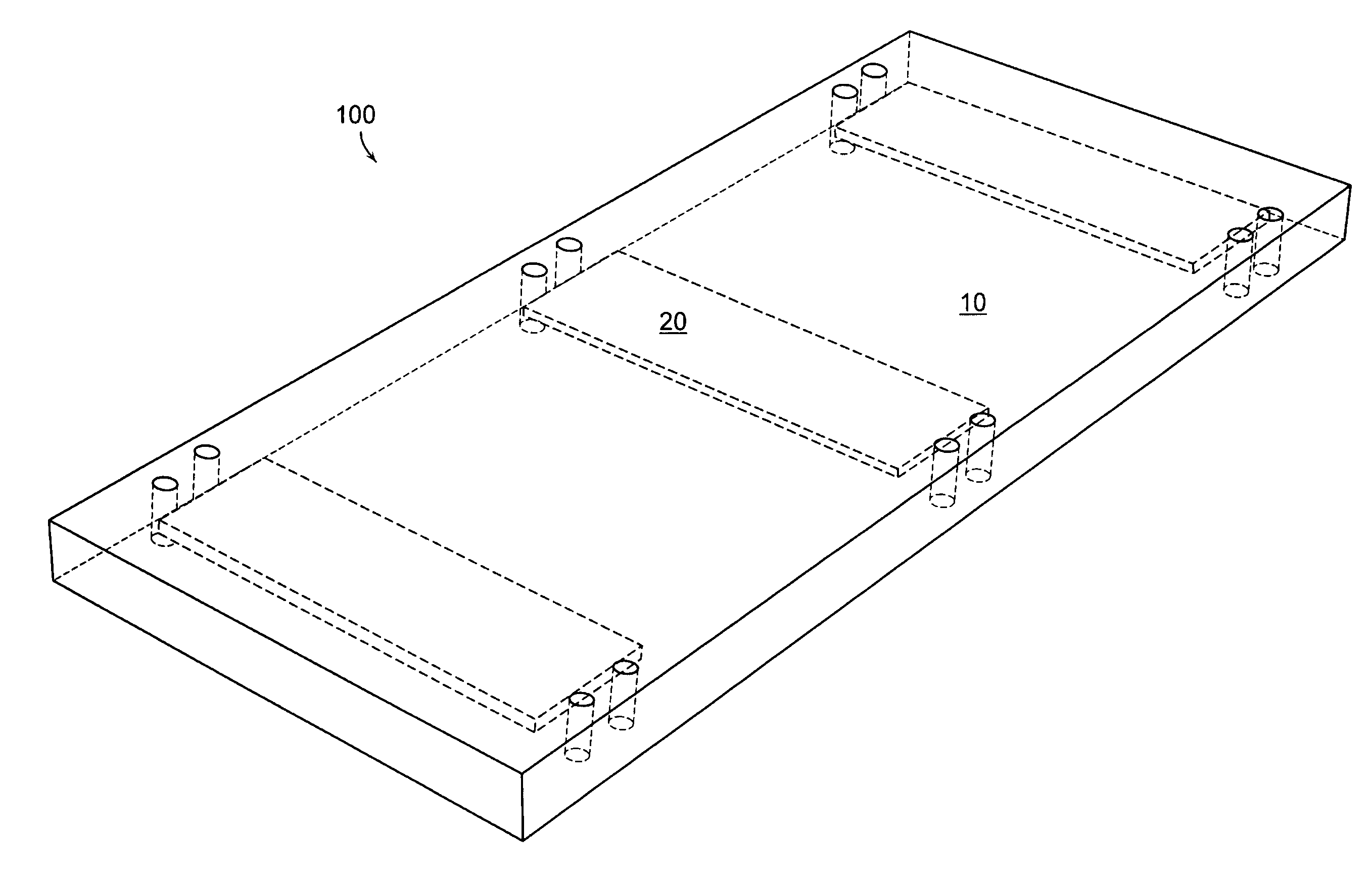
[0035]FIG. 6 is a perspective view illustrating the structure of an end plate in accordance with a preferred embodiment of the present invention, and FIG. 7 is a cross-sectional view illustrating the structure of the end plate in accordance with a preferred embodiment of the present invention.

[0036]The end plate 100 for a fuel cell stack in accordance with a preferred embodiment of the present invention is composed of a base material 10 and a plurality of reinforced materials 20 having different coefficients of thermal expansion such that, after the end plate 100 is connected to the fuel cell stack, the middle portion thereof is bent inwardly and the...


PUM

PropertyMeasurementUnit
Temperatureaaaaaaaaaa

Abstract

The present invention provides an end plate for a fuel cell stack and a method of manufacturing the same, in which the end plate connected to each of both ends of a fuel cell stack is manufactured in a hybrid structure using two kinds of materials having different coefficients of thermal expansion, thus providing a uniform surface pressure in the fuel cell stack.

Description

CROSS-REFERENCE TO RELATED APPLICATION[0001]This application claims under 35 U.S.C. §119(a) on Korean Patent Application No. 10-2007-0111877, filed on Nov. 5, 2007, the entire contents of which are incorporated herein by reference.BACKGROUND[0002](a) Technical Field[0003]The present invention relates to an end plate for a fuel cell stack and a method of manufacturing the same. More particularly, the present invention relates to an end plate for a fuel cell stack and a method of manufacturing the same, in which the plate to be connected to each of both ends of a fuel cell stack is manufactured in a hybrid structure using two kinds of materials having different coefficients of thermal expansion, thus providing a uniform surface pressure in the fuel cell stack.[0004](b) Background Art[0005]A polymer electrolyte membrane fuel cell (PEMFC) is a device that generates electricity with water produced as a result of an electrochemical reaction between hydrogen and oxygen. The PEMFC can be ap...

Claims


Application Information

Patent Timeline
IPC IPC(8): H01M8/02B29C39/02
CPCH01M8/0223H01M8/0247Y02E60/50H01M8/248H01M8/2465Y02P70/50H01M8/02H01M8/24
Inventor SUH, JUNG DO
Owner HYUNDAI MOTOR CO LTD
Learn More