Quality assurance system and method for point-of-care testing

Active Publication Date: 2009-05-07
ABBOTT POINT CARE
16 Cites 56 Cited by

AI-Extracted Technical Summary

Problems solved by technology

However, the required precision and accuracy of the latter group is not considered to be of the same level of quality as provided by a regulated clinical blood testing laboratory.
Skilled users, e.g. clinical laboratory technicians, are required to run the testing systems, and the systems are generally categorized by the regulatory agency as moderately complex.
While it is desirable that any analytical system always runs within specifications, the complexity of this equipment is often at odds with such a desire.
In some cases, cartridges, such as those supplied by i-STAT Corporation, have a shelf-life of about six to about nine months when refrigerated, but only a limited shelf-life, e.g., about two weeks at room temperature, or, more specifically, about two weeks at up to about 30° C. As a result, a hospital will generally store cartridges at a central refrigerated location, and deliver cartridges to specific departments as demand requires.
These departments may or may not have available refrigerated storage, and this ...

Benefits of technology

[0019]A system and method are disclosed for an improved quality assurance system and method for point-of-care testing. In accordance with exemplary embodiments of the present invention, according to a first aspect of the present invention, a system for performing quality assurance of a quantitative physiological sample test system without using a quality control sample includes a thermal and temporal stress monitor module. The thermal and temporal stress monitor mod...

Abstract

An improved quality assurance system and method for point-of-care testing are disclosed. The present invention provides quality assurance for laboratory quality tests performed by a blood analysis system or the like at the point of patient care without the need for running liquid-based quality control materials on the analysis system. Quality assurance of a quantitative physiological sample test system is performed without using a quality control sample by monitoring the thermal and temporal stress of a component used with the test system. Alert information is generated that indicates that the component has failed quality assurance when the thermal and temporal stress exceeds a predetermined thermal-temporal stress threshold. Alternatively, the present invention provides quality assurance for laboratory quality tests performed by a blood analysis system or the like at the point of patient care by minimizing the need for running liquid-based quality control materials on the analysis system.

Application Domain

Thermometer detailsThermometers using mean/integrated values +7

Technology Topic

Quality assurancePatient care +5

Image

  • Quality assurance system and method for point-of-care testing
  • Quality assurance system and method for point-of-care testing
  • Quality assurance system and method for point-of-care testing

Examples

  • Experimental program(3)

Example

Example 1
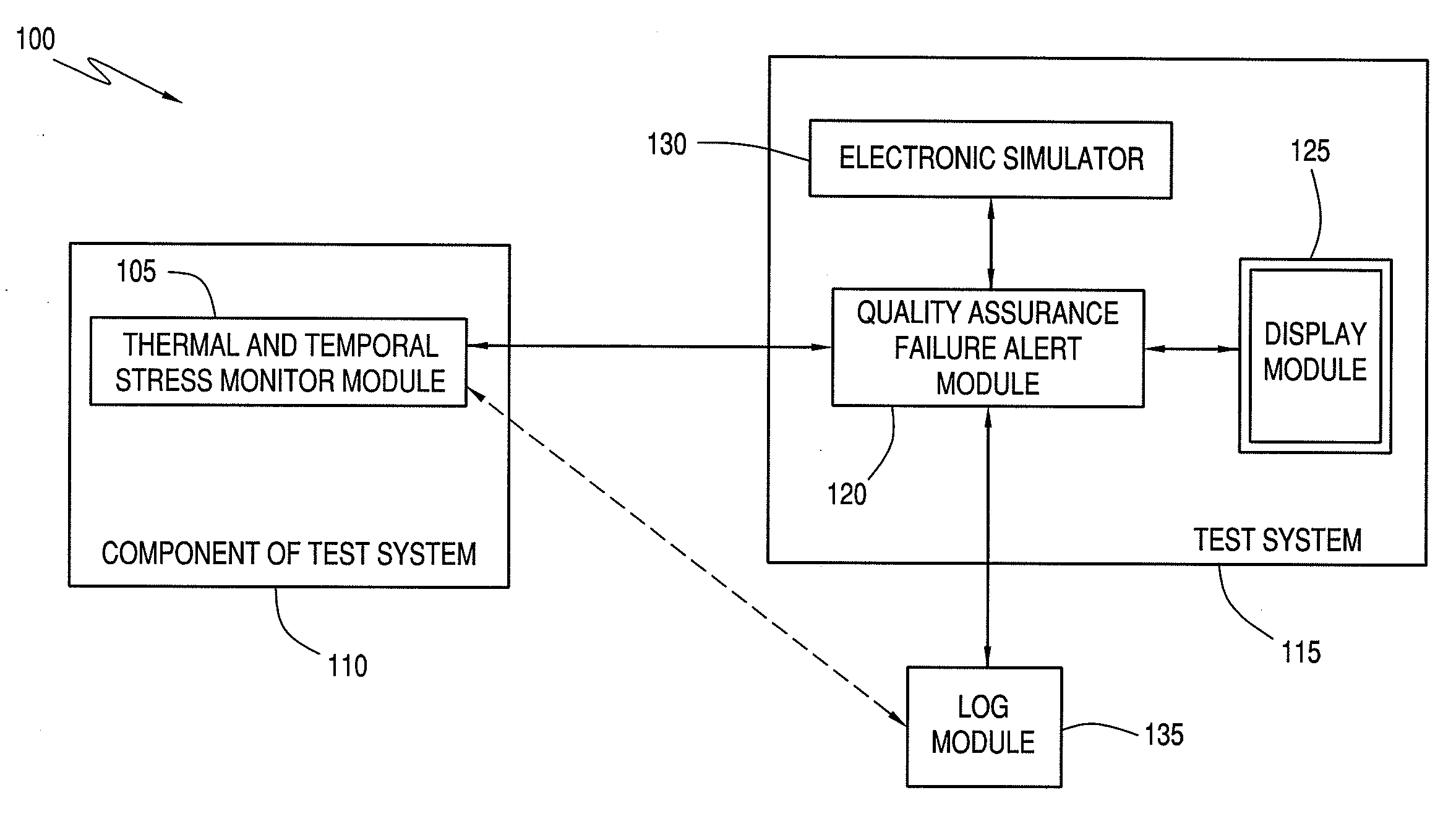
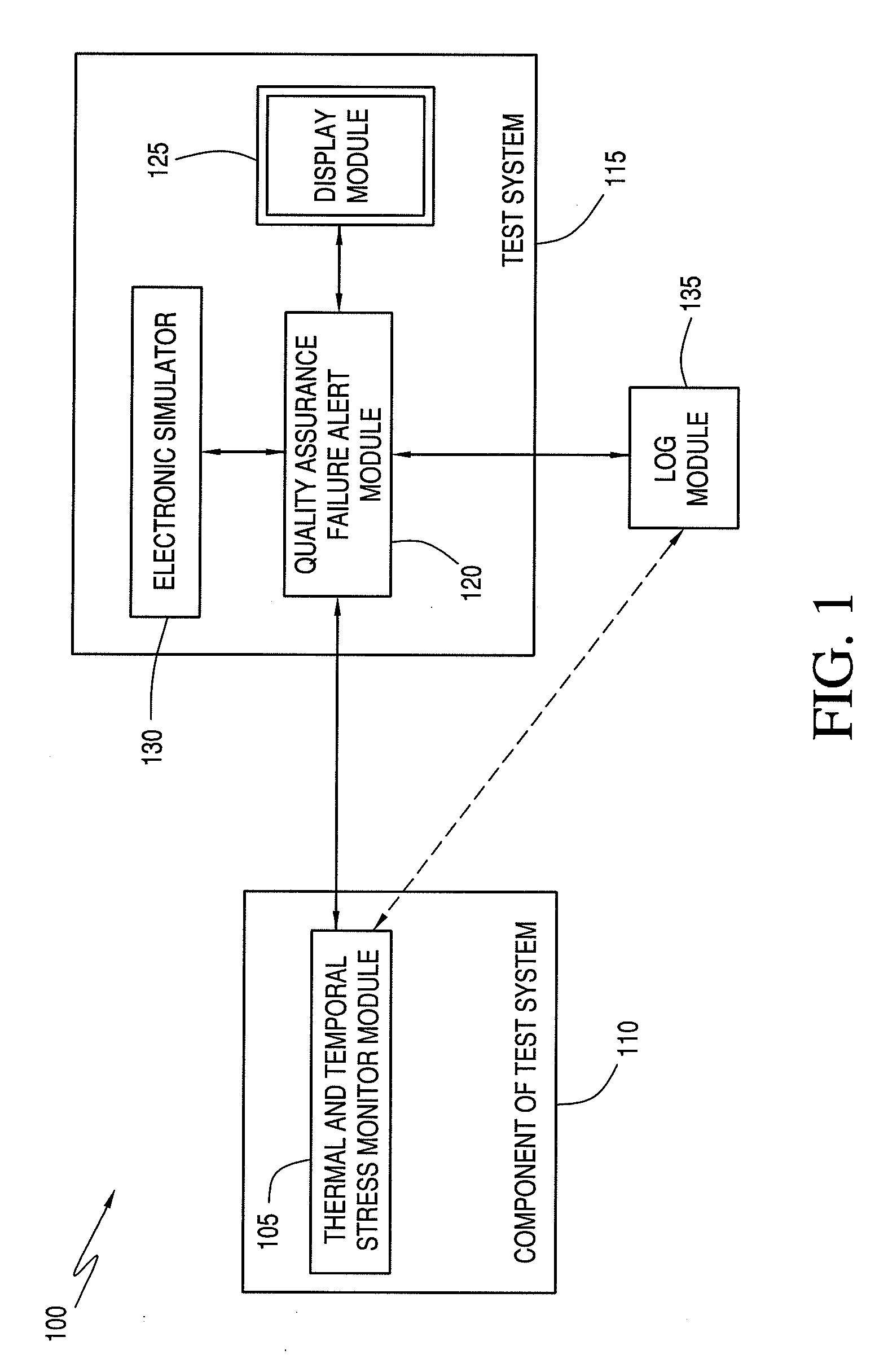
[0106]Verify the presence of calibration fluid. Calibration fluid may not be present if cartridge handling has ruptured the calibration fluid package within the cartridge. The verification is achieved by a measurement of electrical resistance across the sensor area of the cartridge. Failure to achieve an expected resistance in such a failsafe test results in the suppression of the analytical result and display of an error message to the user (e.g., via the display module 125).

Example

Example 2
[0107]Verify the sample was properly positioned within the sample chamber. If the sample volume inserted into the cartridge is either too great or too little, expected characteristics of the electrical signal between sensors will not be attained. Failure to achieve an expected result in such a failsafe test results in the suppression of the analytical result and display of an error message to the user (e.g., via the display module 125).

Example

Example 3
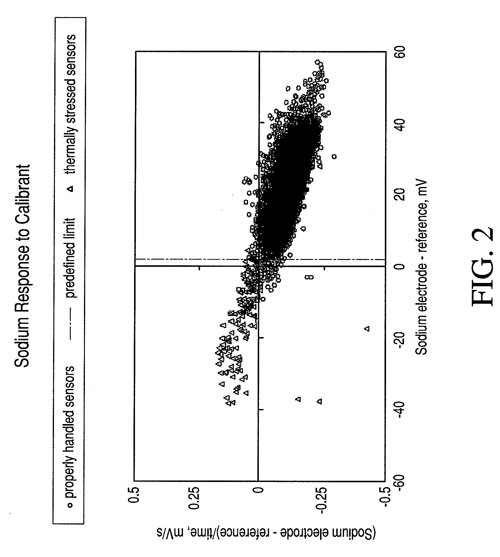
[0108]Verify the ambient temperature is within range. An electronic thermometer in the test system 115 records the ambient temperature. If the ambient temperature is outside the specifications, an error message is presented to the user (e.g., via the display module 125), and the test cycle is not initiated. Experimental support for the applicability of such a failsafe test was obtained by intentionally exposing cartridges to thermal stress. Graphical representations of such a phenomenon are illustrated in FIGS. 2, 3, and 4 for sodium, blood urea nitrogen, and calcium, respectively, which are x-y plots of cal-volt data (x-axis) versus cal-drift (y-axis). These plots include the current system cal-volt and cal-drift threshold limits.
[0109]According to an exemplary embodiment, if the failsafe was triggered by an operator error or component 110 fault, the user is informed and instructed via display module 125 to run another component 110. Such a failsafe protects against systematic error introduced by user technique or damage to a batch, group or set of components 110. Furthermore, if the failsafe was triggered by a fault in the test system 115, the user is instructed on the display module 125 to correct the causative condition, e.g. low battery, temperature out of range, expired software, or the like. Where the causative condition is not correctable by the user, the display module 125 can display instructions for the user to engage the manufacture's technical services department, for example, to obtain a replacement test system 115. Additionally, such information can be provided to the user in an appropriate user manual from the manufacturer that describes the features and operation of the test system 115.
[0110]As discussed previously, the test system 115 can include the automated operation of an internal electronic simulator 130. For example, the electronic simulator 130 can be a separate circuit or device within the test system 115 that is configured to simulate signals produced by the component 110. These simulated signals can be routed to the measurement circuits of the test system 115 to provide an independent confirmation of calibration, such as described in, for example, commonly-assigned U.S. Pat. No. 5,124,661, entitled “Reusable Test Unit for Simulating Electrochemical Sensor Signals for Quality Assurance of Portable Blood Analyzer Instruments.” In a preferred embodiment, the check performed by the electronic simulator 130 can be automatically run every 24 hours, although any suitable time period can be used. The electronic simulator 130 can be used to check that the internal connector that contacts each component 110 is free from material that could cause stray conductive paths, i.e., compromise the integrity of the connector, and that the operational amplifiers that amplify the electrochemical signals from the sensors are within specifications. In other words, the electronic simulator 130 can be configured to generate simulation signals for testing electrical integrity of an electrical connector associated with the test system 115 and/or operational integrity of operational amplifiers associated with the test system 115. If the electronic simulator 130 check fails, the test system 115 will subsequently not process a component 110 and alert the user to the reason of the failure through the display module 125. As the causative condition for the amplifier test is not correctable by the user, either the display module 125 or manual can instruct the user to engage the manufacture's technical services to obtain a replacement test system 115. Where the causative condition is dirt on the connector, the user can be directed to a cleaning protocol to remove the dirt.
[0111]Thus, unlike conventional methods where external liquid control materials are used with the test system 115 (e.g., cartridge-reader combination) for purposes of quality control, exemplary embodiments of the present invention no longer require such external liquid control materials, as the combination of quality control measures described above and herein is sufficient for reliable use. However, it is noted that external liquid control materials can still be provided for use with the test system 115, as such materials can be useful as, for example, a blood substitute for training and general system troubleshooting.
[0112]In addition, unlike conventional in vitro diagnostic systems that provide test results with a precision of better than about 10%, exemplary embodiments of the present invention do not require such external controls to minimize the rate of erroneous results. The rationale is illustrated in a preferred embodiment, notably the i-STAT blood testing system comprising the i-STAT 1 handheld analyzer used in combination with the CHEM8+ cartridge, all available from i-STAT Corporation. The CHEM8+ cartridge performs blood tests with electrochemical sensors for sodium, potassium, chloride, calcium, glucose, total carbon dioxide, blood urea nitrogen, creatinine, and hematocrit, and provides calculated values for several other parameters. Other than thermal stress of the cartridges (e.g. CHEM8+), the design of the i-STAT system eliminates sources of systematic error (e.g., the operator-induced influences described above) that external liquid quality controls had previously been required for detecting. Such systematic errors include operator-induced influences described above that can be managed with failsafe mechanisms and the electronic simulator 130. Furthermore, exemplary embodiments of the present invention provide the inherent benefit of a unit-use analytical system compared to a multi-use one. More specifically, as the sensors and flow-paths in the CHEM8+ cartridge are stored dry, the sensors and flow-paths are not exposed to potential sources of systematic error from repeated exposure to fluids, such as, for example, leaching of sensor active material and protein contamination, as is well-known for multi-use testing systems.
[0113]Another beneficial feature of the present invention is a form of factory-established calibration in which the accuracy of the component 110 readings is confirmed in the factory prior to shipment to the user. As the calibration is factory set and the test system 115 is explicitly designed to lack means for the user to change or alter that calibration in any way, there is no mechanism for the user to misadjust calibration of the test system 115. As a result, systematic error from calibration can be substantially, if not completely, eliminated. A further beneficial feature of the present invention is environmental control. For the exemplary embodiment in which the components 110 comprise cartridges, each test cartridge can be individually packaged in a sealed pouch, such as, for example, foil or a foil-buttercup combination, to provide controlled humidity during storage.
[0114]According to exemplary embodiments of the present invention, it has been found that the aforementioned quality control methodology provides excellent protection against systematic error, because the selected storage limitations are sufficiently conservative for application to point-of-care blood testing or other like testing. Such results are illustrated in FIGS. 5, 6 and 7, in which monitoring occurs with respect to a selected thermal stress threshold value that is a combination of time and temperature. Each figure illustrates the size of the systematic analytical bias induced by imposing a thermal stress beyond one of the stated limits. In particular, FIG. 5 is a graphical representation illustrating the stability beyond labeled conditions, one month beyond the printed expiration date, for an i-STAT CHEM8+ cartridge containing sensors for sodium, potassium, chloride, calcium, glucose, total carbon dioxide, blood urea nitrogen, creatinine and hematocrit. The change in induced bias versus the control condition allowable total error (ATE) is plotted for each test. FIG. 6 is a graphical representation illustrating the stability beyond labeled conditions, eight weeks beyond the printed expiration date at 25° C., for an i-STAT CHEM8+ cartridge containing sensors for sodium, potassium, chloride, calcium, glucose, total carbon dioxide, blood urea nitrogen, creatinine and hematocrit. The change in induced bias versus the control condition ATE is plotted for each test. In particular, FIG. 6 illustrates the analytic bias observed for cartridges that were left at room temperature for 8 weeks compared to cartridges stored in the refrigerator for the same 8 week period. It is noted that in the example illustrated in FIG. 6, the manufacturer's stated non-refrigerated shelf-life for these cartridges is 2 weeks. FIG. 7 is a graphical representation illustrating the stability beyond labeled conditions, three weeks beyond the printed expiration date at 30° C., for an i-STAT CHEM8+ cartridge containing sensors for sodium, potassium, chloride, calcium, glucose, total carbon dioxide, blood urea nitrogen, creatinine and hematocrit. The change in induced bias versus the control condition ATE is plotted for each test.
[0115]The height of each bar in FIGS. 5-7 represents the bias as a percentage of the ATE established for each specific analyte, as illustrated in FIG. 8(A). FIG. 8 illustrates (A) a table for ATE acceptance criteria, (B) an LER (limits for erroneous results) acceptance criteria table for electrolytes, glucose and hematocrit tests, and (C) LER acceptance criteria table for blood urea nitrogen and creatinine tests, in accordance with an exemplary embodiment of the present invention. Data in FIGS. 5-7 are provided using the LER for each test (see FIGS. 8(B) and 8(C)), as required by the FDA. The term ATE will be familiar to those skilled in the art of clinical chemistry. The ATE limits describe expectations for agreement between two analytical methods. The ATE limit is an indication of the accuracy of each test, as described in, for example, FDA Draft Guidance for Waiver (September 2005). The ATE values in the figures are derived directly from the United States FDA Clinical Laboratory Improvements Amendments (CLIA) proficiency testing limits, where such fixed limits are available. For the bars in each of FIGS. 5-7, the even-numbered bars represent measurements using Level 1 control fluid, and the odd-numbered bars represent measurements using Level 3 control fluid. Both control fluids were supplied by i-STAT Corporation, and have concentration value assignments for each analyte that is tested. FIGS. 9 and 10 illustrate anticipated mean reported test values and ranges for these control fluids when run with an i-STAT CHEM8+ cartridge. In particular, FIG. 9 illustrates the expected mean values and ranges for sodium, potassium, calcium, total CO2, glucose, creatinine, chloride and urea controls ((A) Level 1 and (B) Level 3) used with an i-STAT CHEM8+ cartridge that performs these blood tests. FIG. 10 illustrates the expected mean values and ranges for hematocrit controls ((A) Level 1 and (B) Level 3) used with an i-STAT CHEM8+ cartridge that tests for hematocrit among a number of other blood tests.
[0116]It is noted that even after 8 weeks, FIG. 5 illustrates that all the observed biases were significantly smaller than one-half of the associated ATE. It is further noted that these conservative ATE limits also provide a significant cushion to absorb occasional undetected errors or systematic “blind spots,” where a facility is not using automated temperature monitoring. Such a blind spot could be caused by, for example, an unrecognized overnight power failure that allowed refrigerated cartridges to approach room temperature.
[0117]It will be understood by those skilled in the art that a combined thermal and temporal stress value can be based on the integral combination of the two effects in determining the system threshold value, i.e., the predetermined thermal-temporal stress threshold. For example, a threshold value can be exceeded by a significantly elevated temperature excursion for a shorter period, as illustrated in FIG. 11. More particularly, FIG. 11 illustrates the stability beyond labeled conditions, two weeks beyond the printed expiration date at 35° C., for an i-STAT CHEM8+ cartridge containing sensors for sodium, potassium, chloride, calcium, glucose, total carbon dioxide, blood urea nitrogen, creatinine and hematocrit. The change in induced bias versus the control condition ATE is plotted for each test. Again, the even-numbered bars represent measurements using Level 1 control fluid, and the odd-numbered bars represent measurements using Level 3 control fluid. Likewise, the threshold can also be exceeded by a smaller elevated temperature excursion for a longer period, as illustrated in FIG. 7. In another example, the temperature may not have exceeded the designated storage temperature, but the allowable time or shelf-life at that temperature may be exceeded, as illustrated in FIGS. 5 and 6. Thus, the thermal-temporal stress threshold value would be exceeded. The actual predetermined thermal-temporal stress threshold used by the test system 115 for the components 110 will depend on many factors. The guidelines of the general type described in the present disclosure will enable a manufacture to determine how to set a product-specific threshold value.
[0118]It has surprisingly been found that control of storage conditions to such conservative limits, along with the other design elements and failsafe mechanisms discussed above, ensure performance accuracy at a level beyond that which can be ascertained by running multiple cartridges with control solutions that is used in the conventional method of quality control for quantitative measurement using point-of-care blood testing systems. Specifically, users operating under the established conventional method will test cartridges with liquid quality control solutions at the time of supply from the manufacture. Furthermore, it is known that with the conventional method, some users must also re-test on a weekly or monthly basis thereafter to address specific regulatory or facility-specific requirements. Exemplary embodiments of the present invention provide users with a substantial improvement in convenience over the conventional method, and enable and provide for wider adoption of point-of-care testing systems that yield laboratory-grade results in terms of accuracy and precision.
[0119]The College of American Pathologists (CAP) proficiency survey data presented in FIGS. 12-21 illustrate the inherent robustness of exemplary embodiments of the present invention. Proficiency testing is a method by which clinical laboratories are able to demonstrate analytical performance of their instruments. An individual laboratory's analytical results are assessed relative to the analytical performance of the same samples determined on hundreds or thousands of peer laboratories. An expectation for agreement to the peer group is generally three standard deviations (3 sd). Data presented in FIGS. 12-21 reveal excellent precision compared to peer instrument results derived from more than a thousand users. These precision data include all sources of variations, including lot-to-lot variations over many hundreds of lots, and a variety of cartridge age and storage conditions. According to exemplary embodiments, as users of single-use disposable blood testing cartridges have no mechanism or means to adjust test calibration, the only action they could take in response to a performance problem indicated by external liquid quality control solutions would be to take the cartridges out of service.
[0120]Exemplary embodiments of the present invention can also provides a mechanism and methodology of characterizing a manufacturing lot of single-use test devices with respect to end-user quality assurance, where the devices are intended to perform one or more tests to a precision of better than about 10%. The methodology is based on determining the performance of a first portion of the manufacturing lot in the absence of thermal and temporal stress with respect to an allowable total error for each test, and then applying thermal and temporal stresses to one or more other portions of the lot and determining the performance of each portion with respect to the allowable total error for each test. The differences in performance of the first and other portions can then be determined. Such a series of steps provides a methodology for deriving a thermal-temporal stress threshold for use by a test system 115 that uses the lot of components 110. Subsequently, for example, a test system 115 at a point-of-care location can determine whether components 110 from that lot have or have not been exposed to sufficient thermal and temporal stress to be rejected or otherwise prohibited or prevented from use in testing.
[0121]Thus, according to an exemplary embodiment, the component 110 is associated with a batch of substantially similar components 110 in a manufacturing lot. The quality assurance failure alert module 120 can be configured to generate alert information indicating that the batch has failed quality assurance when the thermal and temporal stress of a component 110 of the lot exceeds the predetermined thermal-temporal stress threshold. In other words, the test system 115 can be used to test one or a few components 110 from a manufacturing lot of many components 110. If the quality assurance failure alert module 120 determines that the thermal and temporal stress of the one or few components 110 has exceeded the predetermined thermal-temporal stress threshold, the user can be warned or otherwise notified (e.g., via display module 125) that the entire manufacturing lot must be rejected and must not be used for performing tests. To ensure that users do not obtain test results from these rejected components 110, the test system 115 can suppress display of test results when any of the components 110 in the rejected batch are used with the test system 115.
[0122]As noted previously, each component 110 can comprise, for example, a sensor or the like. According to an alternative exemplary embodiment, an inherent property of a manufactured sensor that changes in response to elevated temperature for a period of time with or without deterioration in sensor performance can be used as a quality control indicator of thermal mismanagement of a cartridge. For example, in potentiometric measurements, such as, for example, pH, sodium and potassium, the Nernstian response of an electrode when contacting calibrant fluid and sample can be unaffected by a prior temperature excursion. However, the calibration potential may have shifted by several millivolts. Accordingly, the test system 115 can register such a change in baseline calibration potential from a value in an anticipated range to one outside that range. Such information can be stored, for example, using the log module 135 or in a memory or other computer storage medium associated with the test system 115 for later retrieval and use by the system. For example, the values in the anticipated range can be stored in a look-up table or other appropriate format. A comparison of the measured calibration potential can be made to the values stored in such a look-up table to determine whether the measured calibration potential is outside the anticipated range. If so, the quality assurance failure alert module 120 can be configured to use the detection of such a change to signal (e.g., via the display module 125) that the component 110 should not be used for patient samples.
[0123]According to an additional exemplary embodiment of the present invention, an internal calibration fluid can be used to detect excessive combined thermal and temporal stress of a component 110. It will be understood by those skilled in the art that certain chemical sensors can be more sensitive to thermal stress (e.g., those containing biochemical entities such as enzymes) than others. As an example, it was found that sensors containing the enzyme urease are significantly more sensitive to thermal stress than hematocrit sensors that do not contain biological entities. In the present additional exemplary embodiment, a number of such sensitive sensors can be used to increase the specificity of combined thermal and temporal stress detection. Such a methodology can improve the effectiveness of the test to determine if the thermal-temporal threshold has been exceeded. For purposes of illustration and not limitation, it has been demonstrated that when predefined limits for signals obtained from urea and ionized calcium sensors are applied, greater than 90% of sensors exposed to thermal and temporal stress are suppressed, as illustrated in FIGS. 2-4.
[0124]In addition, the use of multiple sensors in combination can allow for improved selectivity for the detection of thermal and temporal stress. Such increased selectivity reduces the burden on the user of the component 110, e.g., a nurse, due to the loss of sensors not exposed to combined thermal and temporal stress. Such a method can ensure that components 110 that have been exposed to sufficient thermal and temporal stress, such that they should be rejected from use, are properly identified. However, such a methodology should not have a high false positive rate, i.e., erroneously reject acceptable components 110. In the aforementioned example involving urea and calcium sensors, it was beneficially found that less than 1% of properly handled sensor results were erroneously suppressed, as illustrated in Table 3.
TABLE 3 Calibrant signal analysis Sensors exposed to temporal-thermal stress beyond labeled storage conditions Sensors not exposed to % erroneous % erroneous temporal-thermal stress results reported results reported % results reported with Analyte without failsafe with failsafe failsafe Sodium 24 3 99.6 Potassium 0 0 99.6 Ionized 54 6 99.5 Calcium Chloride 15 6 99.5 BUN 37 13 99.5 GLU 20 3 99.5 CREA 40 4 99.5 TCO2 0 0 99.5
[0125]Application of exemplary embodiments of the present invention will now be described using the i-STAT system as the test system 115 and (single-use disposable) cartridges for components 110 as an example, where the sensors are stored in a dry state prior to use. These sensors must wet-up and equilibrate with a calibrant fluid immediately prior to performing a blood test. It has been found that the transient output signal of these sensors can be used as an indicator of thermal and temporal stress. The present methodology can be generalized as follows. Thermal stress quality assurance of a quantitative electrochemical physiological sample test system 115 is provided by first contacting a number of electrochemical sensors with a calibrant fluid. The calibrant fluid has known concentrations of various analytes to which each sensor is specific. Such contacting is followed by determining a calibration parameter associated with the concentration of an analyte in the calibrant fluid for each of a selected set of the sensors with respect to a thermal check threshold. It is noted that the calibration parameter can be a calibration voltage that is the potential difference in millivolts (mV) between the sensor and a reference electrode, and the thermal check threshold can be a pre-selected voltage level. Alternatively, the calibration parameter can be a calibration voltage drift rate (associated with the wet-up process) expressed in millivolts per second (mV/s). According to another alternative embodiment, the thermal check threshold can be a combination of the two, e.g., the rate of drift after a pre-selected calibration voltage level is attained. In the last step, the methodology disqualifies the test system 115 from performing a physiological sample test when each of the thermal check thresholds is exceeded for the selected set. For purposes of illustration and not limitation, the selected set of sensors can include a sodium ion-selective electrode and a calcium ion-selective electrode, and, optionally, can include a BUN electrode. Where, for example, a cartridge contains multiple sensors, the selected sensors alone can act as a mechanism for determining thermal and temporal stress for the entire device. It is noted that it will be apparent to those skilled in the software art that a computer algorithm can be written embodying the present methodology (e.g., as part of the quality assurance failure alert module 120) and embedded with other software used to automatically operate the test system 115.
[0126]The methodology described above relating to Table 3 was based on accelerated lifetime studies of cartridges containing sensors that are intentionally exposed temporally (for different periods of time) to thermal stress. Analysis of the calibration voltage drift rates and calibration voltages were shown to exhibit changes that can be used to develop an algorithm that identifies thermal and temporal stress. Graphical representations of this phenomenon are illustrated in FIGS. 2-4, which are x-y plots of cal-volt data (x-axis) versus cal-drift (y-axis) for sodium, blood urea nitrogen and calcium, respectively. According to an exemplary embodiment, a version of such an algorithm is as follows:
Step 1: Identify sodium cal-volt (Na VLT c) below thermal check (TC1) threshold.
Step 2: Identify calcium cal-volt (Ca VLT c) below thermal check (TC2) threshold.
Step 3: Suppress results where Na VLT c and Ca VLT c exceed thresholds TC1 and TC2.
For example, the lower limit for Na VLT c can be about 2 mV, and the lower limit for Ca VLT c can be about 30 mV versus an internal silver-silver chloride reference electrode. Various suitable reference electrodes are known in the electrochemical art, as described in, for example, commonly-assigned U.S. Pat. No. 4,933,048.
[0127]According to an exemplary embodiment, the selection of a sub-set of tests, e.g., sodium and calcium, can act as disqualification criterion for a plurality or range of other tests. Thus, quality assurance of a quantitative electrochemical physiological sample test system 115 can be achieved by first contacting a plurality of electrochemical sensors with a calibrant fluid. Subsequently, a calibration parameter associated with the concentration of an analyte in the calibrant fluid can be determined for at least each of a selected sub-set of the plurality of the sensors with respect to a thermal check threshold. The test system 115 can be disqualified from performing a physiological sample test when each of the thermal check thresholds is exceeded for the sub-set. Where the thermal check thresholds are not exceeded, the test system 115 can report the test results in an established manner.
[0128]While the above description addressed the preferred embodiments of the present invention, other related methods for assuring quality are further described below. For example, in an alternative exemplary embodiment of the present invention, each component 110 can incorporate a time-temperature indicator or the like that is capable of showing that a predetermined time-temperature threshold has been exceeded. For example, the time-temperature indicator can be a chemical composition coated onto an adhesive patch that is attached to the component 110. A temperature-dependent chemical reaction or phase change causes a color change that is evident to the user, e.g., green to red. Indicator devices that rely on the chemical properties of pigments to change color over time in response to temperature fluctuations are commercially available, such as OnVu™ (offered by Ciba Specialty Chemicals and FreshPoint (both located in Switzerland)). For example, the quality assurance failure alert module 120 can include or be in communication with a suitable optical mechanism and/or image processing algorithm that is capable of discerning changes in color in the time-temperature indicator once the component 110 is inserted into or otherwise engaged with the test system 115. The user will then discard components 110, as appropriate, from use with patient samples that failed the test.
[0129]In a further exemplary embodiment of the present invention, each individual component 110 includes a mechanism for determining if that component 110 has experienced a temperature-time profile that exceeds the predetermined limit set by the manufacturer. In such an approach, the test system 115 is configured to automatically detect such an occurrence and suppress reporting of results for a patient sample applied to the cartridge. The test system 115 preferably displays the cause (e.g., via the display module 125), and indicate that the sample should be re-tested with another component 110. For example, the determination can be made automatically using the colored patch methodology described above. Accordingly, the test system 115 can include a photodetector or the like that is capable of interrogating the time-temperature patch on the component 110, before or while tests are being run. Where a color change has occurred and been detected, the test system 115 can suppress the patient test results and alert the user.
[0130]In a further exemplary embodiment of the present invention, a temperature-dependent liposomal indicator reagent release step can be used. The concept of using liposomes to discharge molecules from the interior of the liposome into the bulk fluid in a temperature dependent manner is known in the art, as described in, for example: R. L. Magin, “Temperature-Dependent Drug Release from Large Unilamellar Liposomes,” Cancer Drug Deliv., 1, 109-17, 1984; S. B. Tiwari, “Temperature Sensitive Liposomes of Plumbagin,” J. Drug Targeting 10, 585-91, 2002; P. Chandaroy, “Temperature Controlled Content Release from Liposomes Encapsulating Pluronic F127,” J. Controlled Release, 76, 27-37, 2001; and H. Hayashi, “Temperature Sensitive Liposomes Using Copolymers of N-isopropylacrylamide,” Bioconj. Chem. 10, 412-8, 1999.
[0131]In the present invention, a hermetically-sealed calibrant fluid pouch within each component 110 (e.g., as described in commonly-assigned U.S. Pat. No. 5,096,669) can be used to deliver a calibrant fluid to a test chamber of the test system 115 to calibrate the sensors. According to an exemplary embodiment, the fluid pouch can contain temperature-dependent liposomes in the fluid. In one exemplary embodiment, the liposomes can contain a high level of potassium ions, e.g., 50 mM (or any suitable amount), compared to the bulk of the fluid that has a concentration of, for example, 4 mM (or any suitable amount). Where the component 110 has not experienced elevated temperatures, the liposomes remain whole and the bulk concentration remains at 4 mM potassium. However, when an elevated temperature does occur, the liposomes release potassium and the bulk potassium concentration is substantially increased. As the potassium sensor in the test chamber is expecting to see only a 4 mM concentration, an elevated potassium reading in the calibrant fluid will be indicative of the elevated temperature excursion, and such an indication can be used to determine failure of the quality control test. If the potassium is at the anticipated level, the component 110 can be allowed to continue to perform tests and the results can be reported. It is noted that one skilled in the art of electrochemical measurements will recognize that software algorithms embedded in the test system 115 can be used to perform the analysis. For example, commonly-assigned U.S. Pat. Nos. 5,200,051 and 5,112,455 describe the manufacture and use of various sensors including potassium, glucose and blood urea nitrogen (BUN).
[0132]Other alternative exemplary embodiments for using liposomes in the present invention can include detection of the potassium ions released from liposomes by means of a conductivity sensor. It is noted that the hematocrit sensor in an i-STAT cartridge is a conductivity sensor. The increase in potassium ion concentration will be registered by the test system 115 as an unusual elevation in conductivity, associated with the increase in ionic strength of the calibrant fluid, and thus be indicative of a failed quality control test. Furthermore, the liposomes can contain a chemical inhibitor of an enzyme. Such inhibitors are well known in the enzymology art. Sensors in the i-STAT cartridge that measure glucose and BUN, which use the enzymes glucose oxidase and urease, respectively, give an anticipated signal output in the presence of the calibrant fluid that contains known concentrations of glucose and urea. However, where a liposome is incorporated into to the calibrant fluid pouch that contains liposomes with an appropriate enzyme inhibitor, temperature elevation will release the inhibitor and can be detected by the test system 115 due to a lack or reduced signal at the enzymatic sensor. Again, such a situation is indicative of a failed time-temperature quality check, i.e., the thermal and temporal stress exceeding a predetermined thermal-temporal stress threshold level. Known inhibitors of glucose oxidase include copper, silver, and mercury ions, and for urease include various heavy metal ions.
[0133]In an alternative exemplary embodiment, the component 110 can contain a pair of adjacent electrical contacts, where a conductive wax coats the gap between the two contacts. When the wax is exposed to an elevated temperature for a given period, it melts and is wicked into an adjacent chamber. Such a process partially or completely removes the wax from the contacts. When the component 110 is subsequently tested by the test system 115, the test system 115 is able to detect whether there is a conductive path between the two contacts. If there is not, the test system 115 can signal that the component 110 has failed the storage temperature quality assurance test. Electrically conductive waxes are well known in the art, as described in, for example, U.S. Pat. No. 4,098,652, where conduction is based on metal-coated particles mixed into the wax to give the desired electrical properties. Other materials that can act as temperature-time excursion indicators include, for example, liquid crystals. For example, HemoTemp II (available from Biosynergy, Elk Grove, Ill.) is an irreversible liquid crystal time-temperature integrator. In another alternative exemplary embodiment, monitoring can occur with respect to thermal stress by means of thermal detectors, such as, for example, a thermistor, a thermocouple, a thermal ink, a temperature-dependent chemical reaction, a temperature-dependent phase change of a material, and the like. Such devices and materials are well known in the art.
[0134]According to a further exemplary embodiment, the component 110 is stored in a refrigerator below a predetermined threshold temperature value, preferably below about 5° C., but acceptably within the range of about 2° C. to about 8° C. In other words, the component 110 can be stored in a refrigerated enclosure below a predetermined temperature. The refrigerator can be located, and the testing performed, at various suitable locations, including, but not limited to, a hospital central laboratory, a satellite laboratory, a point-of-care location, a patient bedside, a moving vehicle, a laboratory services vendor, and other like locations. Preferably, the component 110 is removed from the refrigerator prior to use with the test system 115, and permitted to attain an ambient temperature (e.g., room temperature range) prior to being used to perform a test. The components 110 can be contained in a box, e.g., a cardboard box containing about 25 cartridges or other suitable amount of cartridges, and the box can contain a single appended thermal stress detector, such as a color changing wax or like temperature-time indicator. According to such an exemplary embodiment, monitoring occurs with respect to a thermal stress threshold and is performed automatically. The thermal stress detector can be separate from an individual component 110, but in substantially the same thermal environment as the component 110 (e.g., being first in the refrigerator and then at ambient room temperature).
[0135]FIG. 22 is a flowchart illustrating steps for quality assurance of a quantitative physiological sample test system performed without running a quality control sample, in accordance with an exemplary embodiment of the present invention. In step 2205, the thermal and temporal stress of a component used with the test system is monitored. When it is desired to run a test using the component and the test system, a component can be obtained from, for example, refrigerated or other appropriate storage in step 2210. In step 2215, a determination is made as to whether the thermal and temporal stress of the component has exceeded a predetermined thermal-temporal stress threshold. If not, then the component can be used with the test system in step 2220. The method can return to step 2210 to obtain another component from storage to perform another test.
[0136]However, if it is determined in step 2215 that the predetermined thermal-temporal stress threshold has been exceeded, then in step 2225, alert information is generated indicating that the component has failed quality assurance, and, therefore, should be discarded. Additionally, the display of the test results can suppressed when the component has failed quality assurance. If the component is associated with a batch or group of substantially similar components, then in step 2230 alert information can be generated indicating that the batch of substantially similar components has also failed quality assurance, and should be discarded.
[0137]A process flow diagram is provided in FIG. 23 that serves to provide additional delineation of exemplary embodiments of the present invention. FIG. 23 is a flowchart illustrating a method of quality control based on automatic thermal and temporal monitoring without the use of control fluids, in accordance with an exemplary embodiment of the present invention. For purposes of present illustration and not limitation, the test system 115 can comprise a suitable reader/analyzer, and the components 110 can comprises (single use, disposable) cartridges. In step 2305, the reader is manufactured at the factory. Additionally, cartridges can be manufactured at the factory in step 2310. In step 2315, factory calibration of the reader is performed to confirm the accuracy of the cartridge readings. As discussed previously, such factory-established calibration can confirm the accuracy of the cartridge readings in the factory prior to shipment to the user. As the calibration is factory-set and the reader is explicitly designed to lack functionality that would allow the user to change or alter that calibration in any way, there is no mechanism for the user to misadjust calibration of the reader. As a result, systematic error from calibration can be substantially, if not completely, eliminated.
[0138]In step 2320, the reader is shipped from the factory to an appropriate facility (e.g., hospital, physician's office, or the like). In step 2325, the cartridges are also shipped to the facility. In step 2330, qualification and verification of the reader by the user occurs after arrival at the facility to ensure that the reader is functioning properly. Additionally, upon arrival at the facility, the cartridges are stored in an appropriate refrigerated environment in step 2335 for later use. When the user desires to use a cartridge (e.g., for performing a suitable test), the user can obtain a cartridge from the refrigerated storage in step 2340. In step 2345, a determination is made as to whether the thermal stress of the cartridge has been exceeded. If so, then in step 2350 the cartridge and the lot of cartridges are rejected. However, if the thermal stress of the cartridge has not been exceeded, then in step 2355, a determination is made as to whether the temporal stress of the cartridge has been exceeded. If so, then the cartridge and the lot of cartridges are rejected (in step 2350). Otherwise, the quality of the cartridge (and the lot) has been assured, and the cartridge (and reader) can be used to run the patient sample to perform the desired test(s).
[0139]The system 100 can include suitable additional modules as necessary to assist or augment the functionality of any or all of the modules of the system 100. For example, the system 100 can include a database module (in addition to the log module 135) that can be in communication with, for example, the quality assurance failure alert module 120. Such a database module can be configured to store any suitable type of information generated or used by or with the system 100, including, for example, thermal/temporal stress recordings, and other like information. Such a database module can be comprised of any suitable type of computer-readable or other computer storage medium capable of storing information in electrical or electronic form.
[0140]Alternative architectures or structures can be used to implement the various functions of the system 100 as described herein. For example, functions from two or more modules can be implemented in a single module, or functions from one module can be distributed among several different modules.
[0141]In particular, FIG. 24 is a block diagram illustrating a system 2400 for thermal and temporal stress quality assurance of a quantitative electrochemical physiological sample test system, in accordance with an alternative exemplary embodiment of the present invention. The system 2400 includes a plurality of electrochemical sensors 2405 (electrochemical sensor 1, electrochemical sensor 2, . . . , electrochemical sensor N, where N is any suitable number). For example, the component 110 can include one or more of the electrochemical sensors 2405. Each of the plurality of electrochemical sensors can comprise any suitable type of sensor or electrode, such as, for example, a sodium sensor, a potassium sensor, a chloride sensor, a pH sensor, a pO2 sensor, a pCO2 sensor, a lactate sensor, a glucose sensor, a creatinine sensor, a BUN electrode, a calcium sensor, a magnesium sensor, a hematocrit sensor, or the like. According to the present exemplary embodiment, the plurality of electrochemical sensors are contacted with a suitable calibrant fluid.
[0142]The system 2400 includes a calibration circuit 2410 in communication with the plurality of electrochemical sensors 2405. For example, the test system 115 can include the calibration circuit 2410 (e.g., as part of or in communication with the quality assurance failure alert module 120). The calibration circuit 2410 is configured to determine a calibration parameter associated with the concentration of an analyte in the calibrant fluid for each electrochemical sensor 2405 of a subset of the plurality of electrochemical sensors 2405 in accordance with a predetermined check threshold. According to an exemplary embodiment, the subset of electrochemical sensors 2405 can comprise, for example, a calcium ion-selective electrode and a BUN electrode. According to an alternative exemplary embodiment, the subset of electrochemical sensors comprise a sodium ion-selective electrode, a calcium ion-selective electrode, and a BUN electrode. However, the subset can include any suitable number and type of electrochemical sensors 2405. The calibration parameter can comprise, for example, a calibration voltage or a calibration voltage drift rate. According to an alternative exemplary embodiment, the calibration parameter can comprise a suitable combination of the calibration voltage and the calibration voltage drift rate. However, any appropriate calibration parameter can be used for purposes of the thermal and temporal stress quality assurance. The calibration circuit 2410 is configured to disqualify the test system from performing a physiological sample test when the predetermined check threshold is exceeded for each electrochemical sensor 2405 of the subset.
[0143]Merely for purposes of illustration and not limitation, the system 2400 can include a first electrochemical sensor 2405 and a second electrochemical sensor 2405. The first and second electrochemical sensors 2405 are each contacted with a calibrant fluid. The calibration circuit 2410 can be configured to determine a first calibration voltage for the first electrochemical sensor 2405 associated with the concentration of a first analyte in the calibrant fluid in accordance with a first check threshold. The calibration circuit 2410 can also be configured to determine a second calibration voltage for the second electrochemical sensor 2405 associated with the concentration of a second analyte in the calibrant fluid in accordance with a second check threshold. The calibration circuit 2410 can be configured to disqualify the test system from performing a physiological sample test when both the first and second check thresholds are exceeded. Appropriate check thresholds can be determined and established in accordance with the methodology discussed herein.
[0144]In the previous discussion, the preferred exemplary embodiments focused on a methodology that entirely removed the need for the use of quality control fluids. In the subsequent description, alternative exemplary embodiments of the present invention focus on a methodology that substantially reduces the need for quality control fluids for quality assurance of point-of-care and bedside testing. Once again, the preferred embodiments will be illustrated with respect to the operation of the exemplary i-STAT system. However, those skilled in the art will recognize that the principles described also apply to other similar clinical sample testing systems.
[0145]It has been discovered that a blood testing cartridge (component 110) that contains various sensors is amenable to quality assurance testing for thermal and temporal stress based on a single control fluid. Here, the testing system 115 of which such a component 110 forms a part is still able to deliver performance precision of better than about 10% for each type of sensor-based test.
[0146]As described above, a user needs to have an accurate and precise analytical measurement. Such a need gives rise to a requirement for a quality check, or a failure alert mechanism, for components 110 that may have had performance compromised by component 110 storage outside the labeled storage recommendations for either or both time and temperature. For purposes of discussion, incorrect storage conditions can be designated as cartridge thermal mismanagement.
[0147]The present alternative exemplary embodiment is best described by contrasting a specific example with the conventional methodology. A given specific example is the i-STAT CHEM8+ cartridge described above that performs a set of chemistry tests and a hematocrit measurement on a single blood sample. The conventional quality assurance methodology for determining thermal stress is to run four separate cartridges, one each with the following quality control fluids: Chemistries Level 1, Chemistries Level 3, RNA Hematocrit Level 1 and RNA Hematocrit Level 3 (see FIGS. 9 and 10). As described above, running four separate cartridges can be burdensome for point-of-care users. However, such a conventional quality assurance methodology reflects the manufacturer's knowledge of product performance (e.g., accuracy, precision) as a function of temperature and time, and has been established such that the boundary conditions are far removed from those time and temperature conditions that give undesirable product performance.
[0148]It is reasonable to expect that the aggregate product performance arises from thermally-induced component 110 changes, as indicated by the accuracy and precision of each sensor. To provide a methodology that uses only a single fluid, it is necessary to evaluate the performance of each individual sensor in the CHEM8+ cartridge as a function of thermal and temporal stress to find the best single control fluid composition that facilitated acceptable quality assurance. Regarding the chemistry tests, FIGS. 5-7 and 11 illustrate that the BUN, creatinine and ionized calcium sensors are the most sensitive to temporal and thermal stress in Chemistries Level 1 and 3, and that these three sensors are more sensitive to Level 1 than Level 3. The experimental evidence indicates that each sensor does not respond equally to thermal and temporal stress, with some sensors being more sensitive than others to thermal and temporal stress. It is apparent from FIGS. 5-7 and 11 that those sensors with lesser sensitivity include sodium, potassium, chloride, total carbon dioxide (TCO2), and glucose.
[0149]It has been found that the hematocrit sensor is insensitive to thermal and temporal stress in RNA Medical Hct control fluids Levels L1 and L3, as illustrated in FIGS. 23(A) and 23(B), respectively. The graphs in FIGS. 25(A) and 25(B) illustrate the behavior of the CHEM8+ hematocrit sensor under thermal stress (T=35° C. for 4 weeks), and compare the performance of cartridges stored at T=5° C. for 1 month to those stored at T=5° C. for 7 months. In FIGS. 25(A) and 25(B), the test fluids used are the RNA Medical hematocrit Levels L1 and L3, respectively (available from RNA Medical, 7 Jackson Road, Devens, Mass. 01434).
[0150]Returning to the three more sensitive tests, BUN, creatinine and ionized calcium (iCa), the rate of change in L1 (Chemistry Level 1 control) concentrations are a function of temperature. Such a result is consistent with a thermally-activated mechanism that can be quantified in an Arrhenius plot. FIG. 26 illustrates a plot of ionized calcium sensors in an i-STAT CHEM8+ cartridge tested with Level 1 chemistry control fluid after various storage times at 5° C., 25° C., 30° C., and 35° C. FIG. 27 is a graphical representation illustrating the data from FIG. 26 as an Arrhenius plot. FIG. 28 illustrates a plot of blood urea nitrogen (BUN) sensors in an i-STAT CHEM8+ cartridge tested with Level 1 chemistry control fluid after various storage times at 5° C., 25° C., 30° C., and 35° C. FIG. 29 illustrates the data from FIG. 28 as an Arrhenius plot. FIG. 30 is a graphical representation of a plot of creatinine sensors in an i-STAT CHEM8+ cartridge tested with Level 1 chemistry control fluid after various storage times at 5° C., 25° C., 30° C., and 35° C. FIG. 31 illustrates the data from FIG. 30 as an Arrhenius plot. It is noted that an Arrhenius plot graphs ln(−Δconc/Δtime) against the inverse of the temperature. Rates of change of concentration over time at all temperatures can be predicted from the Arrhenius equation, allowing for the correlation of short-duration, high-temperature experiments to long-duration, low-temperature experiments.
[0151]In accordance with the data from FIGS. 26-31 (and combined in summary form in FIG. 32), a CHEM8+ cartridge thermal mismanagement quality check can be established using the L1 control fluid. Using these data, the concentration readings of the iCa, creatinine and BUN sensors can be predicted at various storage temperatures over time. Inaccurate results are those that are defined as greater than ATE (e.g., for L1 fluid: iCa: 5%; creatinine: 15%; BUN: 9%). For a given temperature, a predicted time-to-failure can be made, based on the mean reading ≧(target+ATE). Given a normal distribution of concentration reading, the predicted months to failure describes that time at which 50% of results will be inaccurate, i.e., outside the target±ATE. Knowledge of the precision and standard deviation can then be used to adjust the control limits to define a smaller percentage of inaccurate results. For example, a 5% inaccurate result threshold may be desirable. It has been found that the predicted months to failure for the three analytes converge as storage temperature increases. Thus, any one of iCa, BUN or creatinine results in L1 fluid will satisfactorily indicate thermal mismanagement of CHEM8+ cartridges.
[0152]In accordance with such a methodology, the user can implement a thermal mismanagement quality control or failure alert mechanism by a testing protocol using a single cartridge and a single control fluid, per test event. Accordingly, the user can compare the results of the given single cartridge against an acceptable test range (provided by the cartridge manufacture) for iCa, BUN and creatinine analyte results in the L1 fluid. Failure to achieve a result within the specified range for each of the three tests will alert the user to a failure associated with thermal mismanagement. Specifically, the failure alert will be triggered (e.g., by the quality assurance failure alert module 120) if any one analyte is outside the specified target range.
[0153]As discussed previously, it will be understood by those skilled in the art that a combined thermal and temporal stress value can be based on the integral combination of the two effects in determining the system threshold value. For example, a threshold value could be exceeded by a significantly elevated temperature excursion for a short period; likewise, the same threshold could also be exceeded by a smaller elevated temperature excursion for a long period. In another example, the temperature may not have exceeded the designated storage temperature, but the allowable time or shelf-life at that temperature may be exceeded. Consequently, the predetermined thermal-temporal stress threshold value would be exceeded. Experimentation of the general type described in this disclosure will enable a manufacture to determine how to set a product-specific threshold value.
[0154]For ease of presentation, all of the analyte targets available from the L1 fluid can be presented for Na, K, Cl, iCa, glucose, creatinine, BUN and TCO2 in a package insert provided in each box of components 110. By way of example, FIG. 33 illustrates one such package insert layout. It is noted that in FIG. 33, target and range data are omitted for non-critical tests. The following quality control rules can accordingly apply: [0155] If CHEM8+ cartridge expiry date is less than current date, then the cartridge is expired and cartridges from the lot should not be used. [0156] If one of iCa, BUN or Creatinine fail to give a result in the desired range, then consider cartridge lot thermally mismanaged and do not use.
[0157]Those skilled in the art will recognize that while the control fluid composition of Chemistries Level 1 is best suited to determining thermal stress of a CHEM8+ cartridge, other cartridges and components 110 with different test combinations can use a single control fluid with a different combination of analyte concentrations and use one or more different tests to determine thermal mismanagement. Those skilled in the art will also recognize that by using the general principles of the experimental testing process described above for the CHEM8+ cartridge, the skilled artisan can arrive at a suitable composition for a different component 110 with different tests without undue experimentation.
[0158]A process flow diagram is provided in FIG. 34 that serves to provide additional delineation of the present alternative exemplary embodiment of the invention. FIG. 34 is a flowchart illustrating a method of quality control based on thermal and temporal monitoring using a single control fluid or a limited combination thereof, in accordance with an exemplary embodiment of the present invention.
[0159]Merely for purposes of present illustration and not limitation, the methodology illustrated in FIG. 34 will be described in accordance with a reader/analyzer and (single use, disposable) cartridges, although other suitable types of test systems and components can be used. In step 3405, the reader is manufactured. In step 3410, the cartridges are also manufactured. In step 3415, factory calibration of the reader is performed to confirm the accuracy of the cartridge readings. In step 3420, the reader is shipped from the factory to the facility. In step 3425, qualification and verification of the reader by the user occurs after arrival at the facility to ensure that the reader is functioning properly. In step 3420, the cartridges are shipped from the factory to the facility. Upon arrival, in step 3435, a temperature strip or other suitable temperature-time indicator associated with the cartridges is tested or otherwise interrogated to determine whether the thermal-temporal stress of the cartridges was exceeded while in transit. If so, then in step 3440 the entire batch or lot of cartridges is rejected and should not be used.
[0160]If both the qualification/verification of the reader and temperature-time interrogation of the cartridges pass, then in step 3445, liquid quality control measures can be run. In step 3450, the results of the liquid quality control test are recorded. In step 3455, these results are compared to (manufacturer determined) target results for the test system and cartridges. If the liquid quality control test results do not substantially compare with the target results, then in step 3460 the user is instructed to contact the manufacturer's technical support or other appropriate assistance to resolve the problem (e.g., replacement of the reader and/or cartridges). Otherwise, in step 3465, the cartridges are stored in an appropriate refrigerated environment.
[0161]When the user desires to perform a test using the reader and cartridges, in step 3470 the (refrigerated) storage conditions for the cartridges are verified. If the thermal stress of the cartridges has (potentially) been exceeded, then the methodology returns to step 3445 to re-run the liquid quality control measures to determine whether the cartridges can be used. Otherwise, in step 3475, a determination is made as to whether the temporal stress of the cartridges has been exceeded (e.g., whether the expiration date of the cartridges has expired). If so, then the lot of cartridges is rejected in step 3440. Otherwise, the patient samples can be run using the cartridge in step 3480. Once the test(s) have been run, another cartridge can be obtained from (refrigerated) storage. Accordingly, the methodology returns to step 3470 to ensure that the thermal and temporal stress of the cartridges has not been exceeded.
[0162]Each, all or any combination of the steps of a computer program as illustrated in FIGS. 22, 23, and 34, as well as those described herein, for quality assurance of a quantitative physiological sample test system can be embodied in any computer-readable medium for use by or in connection with an instruction execution system, apparatus, or device, such as a computer-based system, processor-containing system, or other system that can fetch the instructions from the instruction execution system, apparatus, or device and execute the instructions. As used herein, a “computer-readable medium” can be any means that can contain, store, communicate, propagate, or transport the program for use by or in connection with the instruction execution system, apparatus, or device. The computer readable medium can be, for example but not limited to, an electronic, magnetic, optical, electromagnetic, infrared, or semiconductor system, apparatus, device, or propagation medium. More specific examples (a non-exhaustive list) of the computer-readable medium can include the following: an electrical connection having one or more wires, a portable computer diskette, a random access memory (RAM), a read-only memory (ROM), an erasable programmable read-only memory (EPROM or Flash memory), an optical fiber, and a portable compact disc read-only memory (CDROM).
[0163]It will be appreciated by those of ordinary skill in the art that the present invention can be embodied in various specific forms without departing from the spirit or essential characteristics thereof. The presently disclosed embodiments are considered in all respects to be illustrative and not restrictive. The scope of the invention is indicated by the appended claims, rather than the foregoing description, and all changes that come within the meaning and range of equivalence thereof are intended to be embraced.
[0164]All United States patents and patent applications, foreign patents and patent applications, and publications discussed above are hereby incorporated by reference herein in their entireties to the same extent as if each individual patent, patent application, or publication was specifically and individually indicated to be incorporated by reference in its entirety.

PUM

no PUM

Description & Claims & Application Information

We can also present the details of the Description, Claims and Application information to help users get a comprehensive understanding of the technical details of the patent, such as background art, summary of invention, brief description of drawings, description of embodiments, and other original content. On the other hand, users can also determine the specific scope of protection of the technology through the list of claims; as well as understand the changes in the life cycle of the technology with the presentation of the patent timeline. Login to view more.
Why Eureka
Try Eureka