Subsea well having a submersible pump assembly with a gas separator located at the pump discharge

a technology of submersible pumps and separators, which is applied in the direction of positive displacement liquid engines, fluid removal, borehole/well accessories, etc., can solve the problem of limited amount of gas acceptable to enter the pump, and achieve the effect of improving the hydraulic efficiency of the system

Active Publication Date: 2009-05-14
BAKER HUGHES INC
View PDF18 Cites 27 Cited by
  • Summary
  • Abstract
  • Description
  • Claims
  • Application Information

AI Technical Summary

Benefits of technology

[0009]This design has the advantages of flow conditioning and some pressure recovery to improve the hydraulic efficiency of the system. Dispersal of gas homogeneously through the intake liquid is a significant aspect of pumping gassy fluids. The same venturi also may be linked at the vena contracta to a gas accumulation location in order to draw in and mix any gas accumulations. In one embodiment, the recycled liquid stream has entrained gas bubbles that are less than approximately 10 μm in size. A limited amount of gas acceptably enters the pump since a separator can only achieve one relatively clean stream.

Problems solved by technology

A limited amount of gas acceptably enters the pump since a separator can only achieve one relatively clean stream.

Method used


Image

  • Subsea well having a  submersible pump assembly with a gas separator located at the pump discharge
  • Subsea well having a  submersible pump assembly with a gas separator located at the pump discharge
  • Subsea well having a  submersible pump assembly with a gas separator located at the pump discharge

Examples


Embodiment Construction

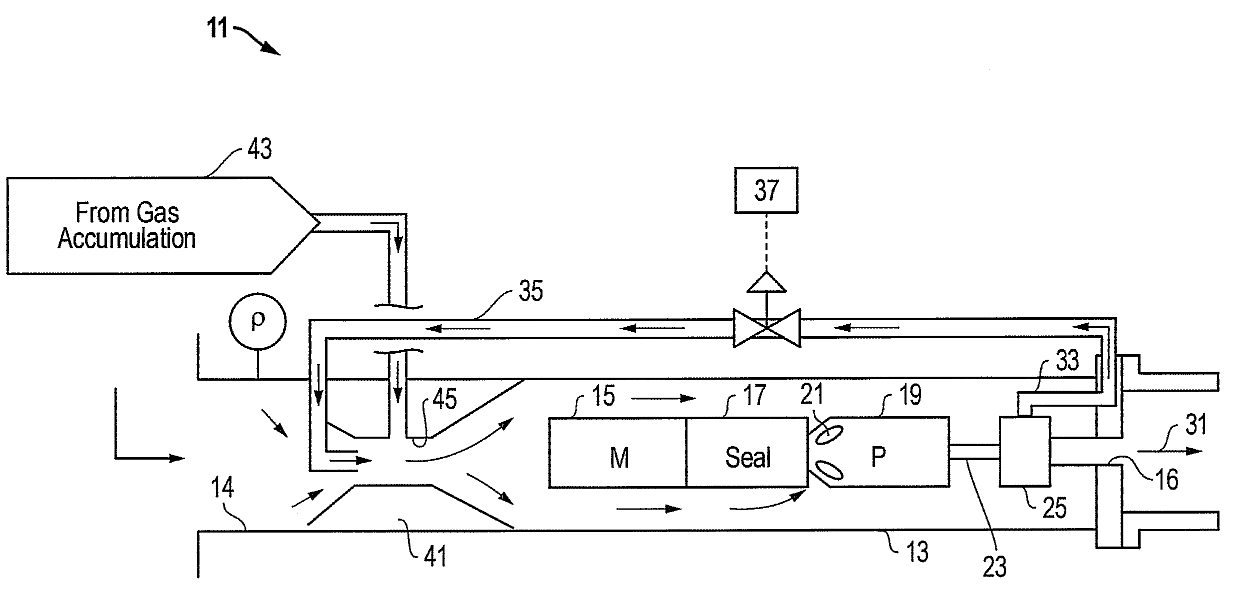
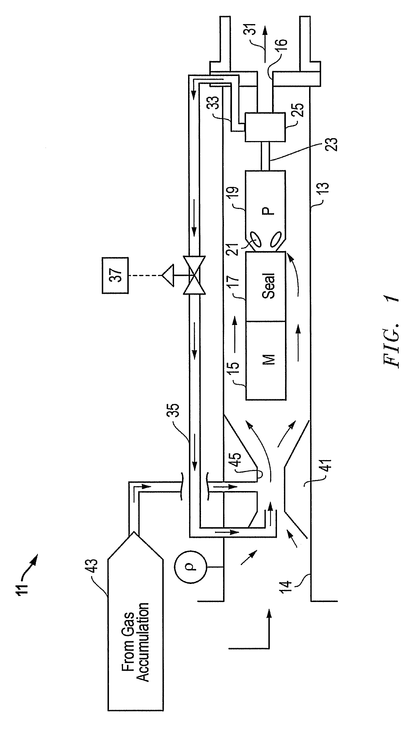
[0015]Referring to FIG. 1, embodiment of a system, method and apparatus for a subsea well having a submersible pump assembly with a gas separator are shown and described. The submersible pump assembly 11 may be located within a capsule 13 having an inlet 14 for receiving intake fluids having mixed liquids and gas, and an outlet 16 for discharging outlet fluid. Alternatively, the components of the submersible pump assembly 11 may be secured to each other inside a permanent well casing 13.

[0016]The pump assembly 11 may be supported by a support (not shown) located on the lower (i.e., left) side of housing 13. A variety of other devices could be employed to mount the pump assembly 11 within housing 13. The pump assembly 11 may be secured to the support to transmit thrust to the housing 13. Pump assembly 11 is of a type that is conventionally installed downhole within a subsea well for pumping well fluids to the surface.

[0017]The pump assembly 11 includes a submersible electrical motor ...


PUM


Abstract

A subsea rotary gas separator system has a separator located adjacent the discharge of the pump for separating gas from the high pressure liquid stream exiting the pump. Some of the high pressure liquid is recycled back to the inlet of the pump to maintain a liquid-rich inlet stream for the pump.

Description

BACKGROUND OF THE INVENTION[0001]1. Technical Field[0002]The present invention relates in general to downhole gas separators and, in particular, to an improved system, method, and apparatus for a submersible pump assembly having a gas separator that produces a liquid stream for reintroduction upstream of the pump.[0003]2. Description of the Related Art[0004]Subsea wells typically connect to a subsea manifold that delivers the well fluid to a production platform for processing, particularly for the removal of water and gas. The oil is then transmitted to a pipeline or other facility for export from the production platform. Production of fluids from a medium to deep subsea environment requires compensation for the effects of cold temperatures, high ambient pressures and fluid viscosity as a function of break out of gas in the fluid stream. In flowing wells, particularly those with light API fluid, these conditions may be mitigated by the nature of the producing reservoir. In wells wit...

Claims


Application Information

Patent Timeline
Patent Type & Authority Applications(United States)
IPC IPC(8): E21B43/40
CPCE21B43/38E21B43/128E21B43/36
Inventor SHAW, CHRIS K.
Owner BAKER HUGHES INC
Why Eureka
Try Eureka