Electric Power Steering Device

a technology of electric power steering and steering wheel, which is applied in electrical steering, mechanical energy handling, transportation and packaging, etc., can solve the problems of increased number, higher production cost, and heavy load on the workers involved, and achieve the effect of convenient assembly and mounting

Inactive Publication Date: 2009-05-14
NSK LTD
View PDF9 Cites 29 Cited by
  • Summary
  • Abstract
  • Description
  • Claims
  • Application Information

AI Technical Summary

Benefits of technology

[0011]The present invention provides an electric power steering device which, having a minimum number of parts, can be easily assembled and mounted on a vehicle. In the electric power steering device, external surface portions of the gear box of a reduction gear mechanism are used as mounting faces for plural circuit modules of a control drive circuit device, enabling the reduction gear mechanism and the plural circuit modules to be integrally assembled with minimum distances among them.
[0012]Integrally mounting plural circuit modules, which are included in a control drive circuit device, on external surface portions, predetermined as mounting faces for the plural circuit modules, of the gear box of a reduction gear mechanism does not require the gear box and other structural members to be enlarged. This facilitates designing a shock absorbing mechanism which requires an adequate length of collapsible stroke for shock absorption to be secured.
[0013]Using predetermined external surface portions of the gear box of the reduction gear mechanism as mounting faces for the circuit modules included in the control drive circuit device makes it possible to design, with flexibility in terms of device shaping, an overall layout of the electric power steering device to be mounted on a vehicle and to easily prevent the electric power steering device, when being mounted on the vehicle, from interfering layoutwise with other devices and parts. This eventually makes it possible to integrate the mechanical mechanism section and electric circuit modules of the electric power steering device and to make the electric power steering device as a whole smaller.
[0014]Furthermore, fixedly mounting the circuit modules of the control drive circuit device on external surface portions, predetermined as mounting faces for the circuit modules, of the gear box of the reduction gear mechanism makes it possible to radiate the heat generated in the power module, i.e. the drive electric circuit board of the control drive circuit device and to prevent the gear box housing from thermally expanding and shrinking to change the clearance between the mutually meshing portions of the worm gear and the worm wheel gear included in the reduction gear mechanism, so that effects of variation in the clearance (for example, effects such as excessively large play between the gears meshing with each other, larger rattling, shortening of the lives of the gears, and degradation of the operational feeling obtained when operating the electric power steering device) can be prevented.
[0015]Still furthermore, integrally mounting the plural circuit modules included in the control drive circuit device on mounting faces provided in predetermined external surface portions of the gear box of the reduction gear mechanism makes it possible to interconnect the plural circuit modules using electrical wirings of minimum lengths, to connect the circuit modules and other circuit device elements using electrical wirings of minimum lengths, and to thereby reduce, to a maximum extent, the wiring loss and improve the energy consumption efficiency of the electric power steering device.

Problems solved by technology

Such an arrangement in which the circuit modules are discretely disposed, however, increases the number of parts required and the numbers of man-hours for assembling the device itself and for mounting the assembled device on a vehicle, resulting in heavier loads on workers involved and a higher production cost.
Using a large gear box housing makes it difficult to secure space where the electric power steering device can be mounted without interfering with other devices, while also resulting in less flexibility in designing an overall layout of devices to be mounted on the vehicle.
Using a large gear box housing makes it difficult for such a shock absorbing mechanism to secure a collapsible stroke long enough to achieve shock absorption.
Thus, there has been a potential problem that an electric power steering device like the above-described cannot meet basic functional requirements to be met by a device included in a steering mechanism system.
Furthermore, there has also been a potential problem with the method of releasing the heat generated in a power module.
With the gear box used as a heat sink, however, the gear box housing is caused to thermally expand and shrink.
Thus, there have been potential operational problems such as that, when the clearance between the gears meshing with each other widens, rattling of the gears becomes louder and that, when the clearance between the gears meshing with each other narrows, the friction between the gears increases to degrade the operational feeling obtained when operating the electric power steering device or to shorten the lives of the gears.

Method used


Image

  • Electric Power Steering Device
  • Electric Power Steering Device
  • Electric Power Steering Device

Examples


first embodiment

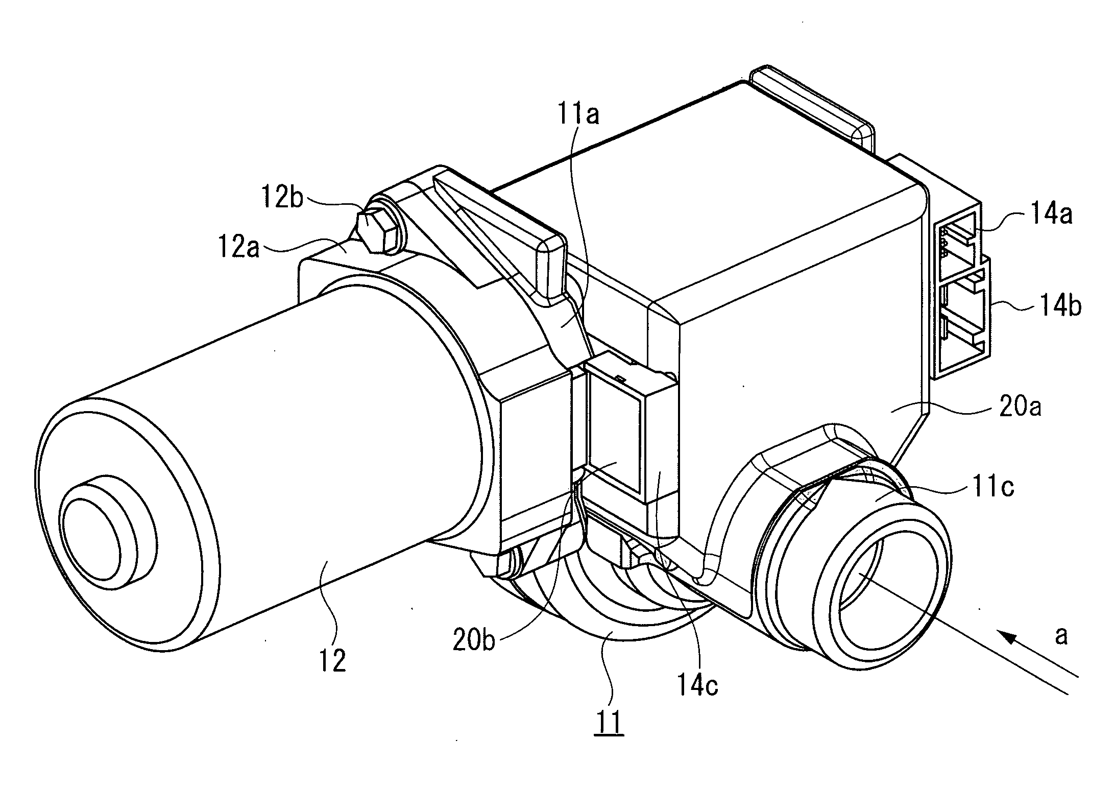
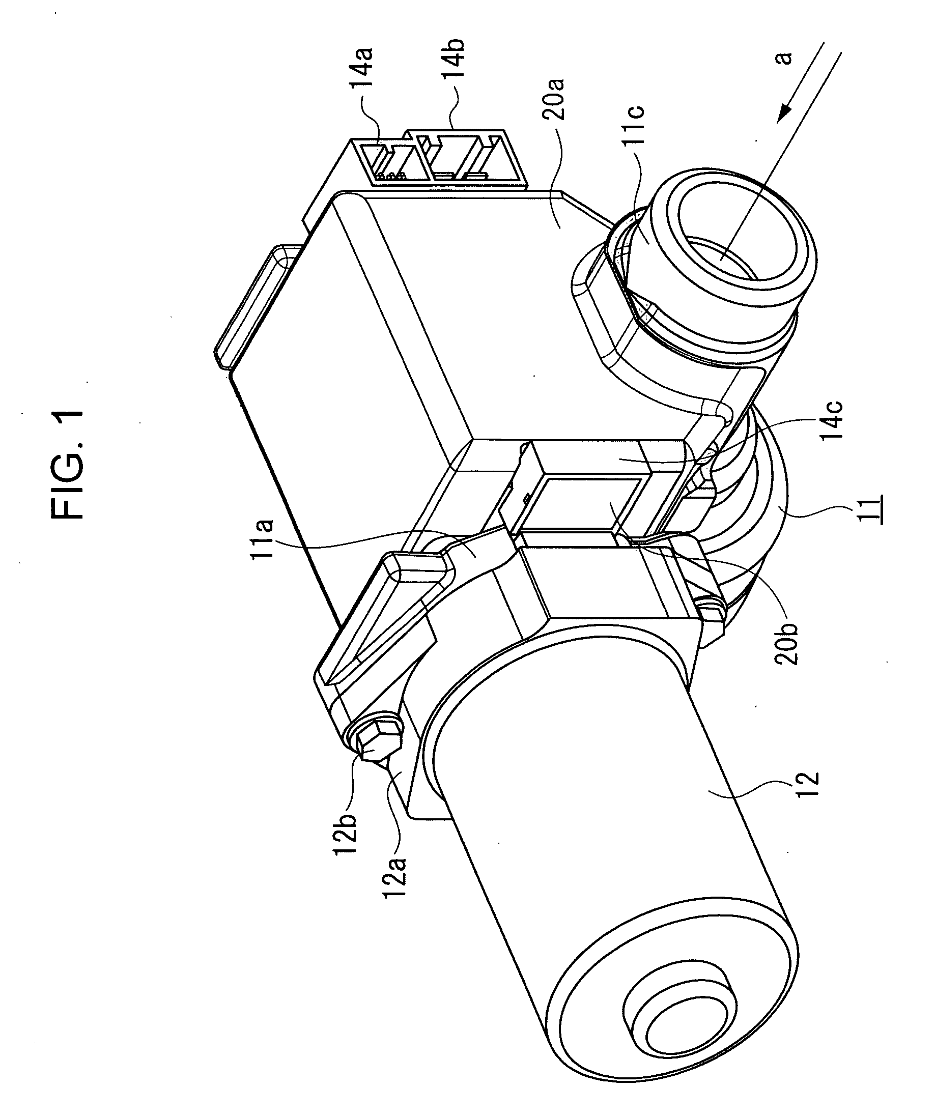
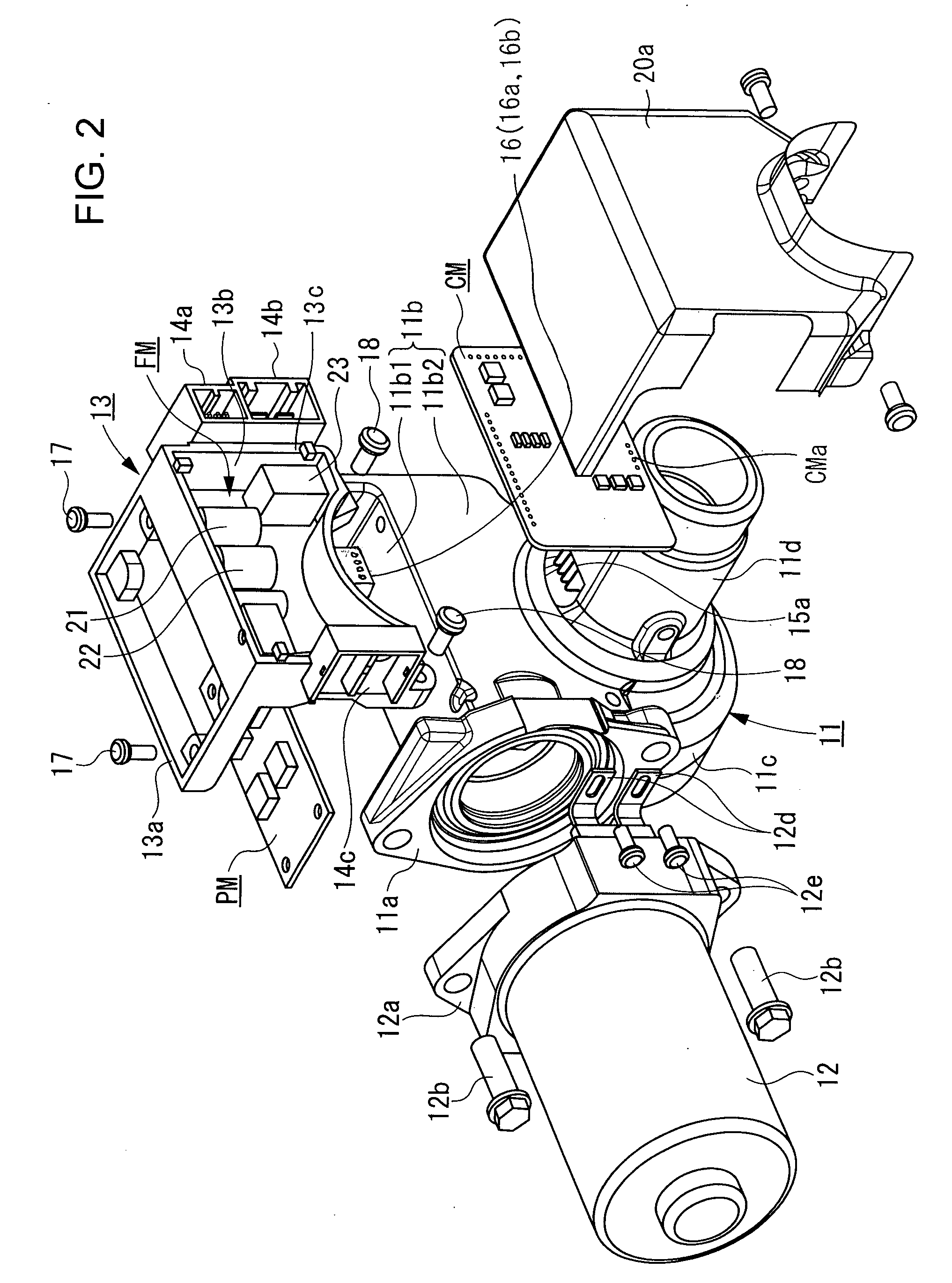
[0033]A first embodiment of the present invention will be described below. FIGS. 1 to 5 are diagrams for explaining the configuration of the electric power steering device according to the first embodiment.

[0034]Referring to FIGS. 1 to 5, reference numeral 11 denotes a gear box of the electric power steering device, and reference numeral 12 denotes an electric motor. In the gear box 11 of the electric power steering device, a reduction gear mechanism is disposed. The reduction gear mechanism includes an input shaft coupled to a steering wheel, a torsion bar, an output shaft, ball bearings, a slide bearing, a worm gear, and a worm wheel gear which are assembled in a configuration similar to a known one shown in FIG. 16. These parts are not shown in FIGS. 1 to 5. Arrow a in FIG. 1 denotes the input shaft to output shaft direction. These parts may be assembled in other than the known configuration shown in FIG. 16.

[0035]The known configuration shown in FIG. 16, for example, is of a col...

second embodiment

[0072]The electric power steering device according to a second embodiment of the present invention will be described below. The electric power steering device of the second embodiment differs from the electric power steering device of the first embodiment in the shapes of the gear box and the module mounting member. As for other constituent parts, the electric power steering device of the second embodiment is the same as the electric power steering device of the first embodiment. In the following, the second embodiment will be described only as to its aspects differing from the first embodiment. Also, parts the same as those used in the first embodiment will be referred to by the same reference numerals as used for the first embodiment, and their description will be omitted.

[0073]FIGS. 10(a) and 10(b) are diagrams for explaining, in outline, a gear box 25 and a module mounting member 26 of the electric power steering device of the second embodiment. FIG. 10(a) shows the gear box 25 ...

third embodiment

[0079]The electric power steering device according to a third embodiment of the present invention will be described below. FIGS. 15(a) and 15(b) are diagrams for explaining, in outline, a gear box 11 and a module mounting member 33 of the electric power steering device of the third embodiment. FIG. 15(a) shows the gear box 11 and the module mounting member 33 in a state where they are not yet fitted together. FIG. 15(b) shows them in a state where they have been fitted together.

[0080]The third embodiment differs from the first embodiment in the inclination angle of the output terminals of the torque detection coil included in the torque sensor and the inclination angle of the through holes formed in the control module.

[0081]In the first embodiment, the output terminals 15a of the torque detection coil 15 of the torque sensor are formed approximately perpendicularly to the second flat face 11b2 of the gear box 11. Also, the front portions of the output terminals 15a of the torque det...


PUM


Abstract

An electric power steering device which has, on the outer surface of its gear box, the circuit modules of a control device such as a power module, a frame module, and a control module, and which is easily mountable on a vehicle and less affected by heating. The upper half of the gear box (11) is formed in a rectangular parallelepiped box (11b) in which a reduction gear mechanism is assembled. The first flat face (11b1) of the gear box (11) on the outside of the axis of the center shaft of an electric motor (12) as viewed from a worm gear meshing point is formed as a mounting face for the power module (PM), and the second flat face (11b2) of the gear box crossing the first flat face is formed as a mounting face for circuit parts forming the frame module (FM) and the control module (CM).

Description

TECHNICAL FIELD[0001]The present invention relates to an electric power steering device for vehicle. It particularly relates to an arrangement and structure for integrally mounting circuit board modules to a mechanical portion of an electric power steering device, the circuit board modules making up an electric circuit device for steering assist control and assist force generation.BACKGROUND ART[0002]A common electric power steering device for vehicle will be described below. In the steering shaft connected between the steering wheel of a vehicle and the pinion shaft included in the rack and pinion steering mechanism of the vehicle, a rotary torque (hereinafter referred to as the “steering torque”) attributable to steering input and output is generated. A torque detection device is provided on the steering shaft to detect the steering torque. Based on the detected steering torque information and vehicle speed information obtained from the vehicle, a varying requirement of steering a...

Claims


Application Information

Patent Timeline
Patent Type & Authority Applications(United States)
IPC IPC(8): B62D5/04
CPCB62D5/0406B62D5/0409H02K11/0073H02K7/1166H02K5/225H02K11/33B62D5/04
Inventor KASHIMOTO, KEIJISHINGOU, MASANORIKAWADA, HIDEAKISHINOHARA, SHIGEOSATOH, KOUICHI
Owner NSK LTD
Why Eureka
Try Eureka