Gas sensor and nitrogen oxide sensor

a technology of gas sensor and nitrogen oxide, applied in the field of gas, can solve the problems of gradual reduction of the sensitivity of the gas sensor to to-be-measured gas components (e.g. nox), and achieve the effects of reducing the sensitivity to to-be-measured gas components, preventing the formation of harmful substances, and high durability

Active Publication Date: 2009-05-14
NGK INSULATORS LTD
View PDF8 Cites 23 Cited by
  • Summary
  • Abstract
  • Description
  • Claims
  • Application Information

AI Technical Summary

Benefits of technology

[0030]In the gas sensor and the nitrogen oxide sensor both of the present invention, a harmful substance in a to-be-measured gas is trapped by the harmful substance-trapping layer, whereby the reduction in sensitivity to to-be-measured gas component, caused by the harmful substance can be prevented. Therefore, the sensor of the pre

Problems solved by technology

When such a gas sensor is fitted to the exhaust system of internal combustion engine (e.g. automotive engine) and the internal combustion e

Method used


Image

  • Gas sensor and nitrogen oxide sensor
  • Gas sensor and nitrogen oxide sensor
  • Gas sensor and nitrogen oxide sensor

Examples


embodiment 1-1

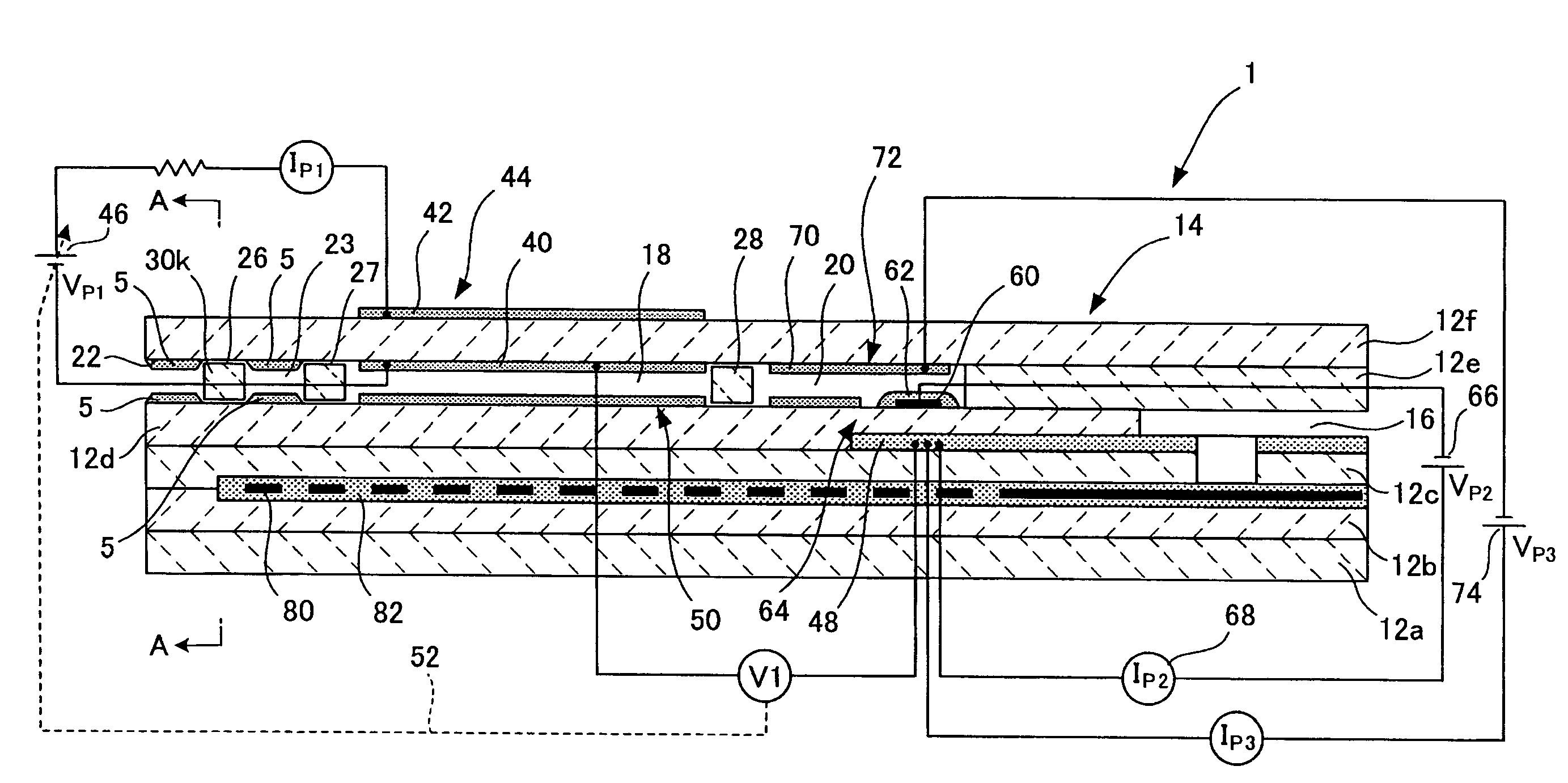
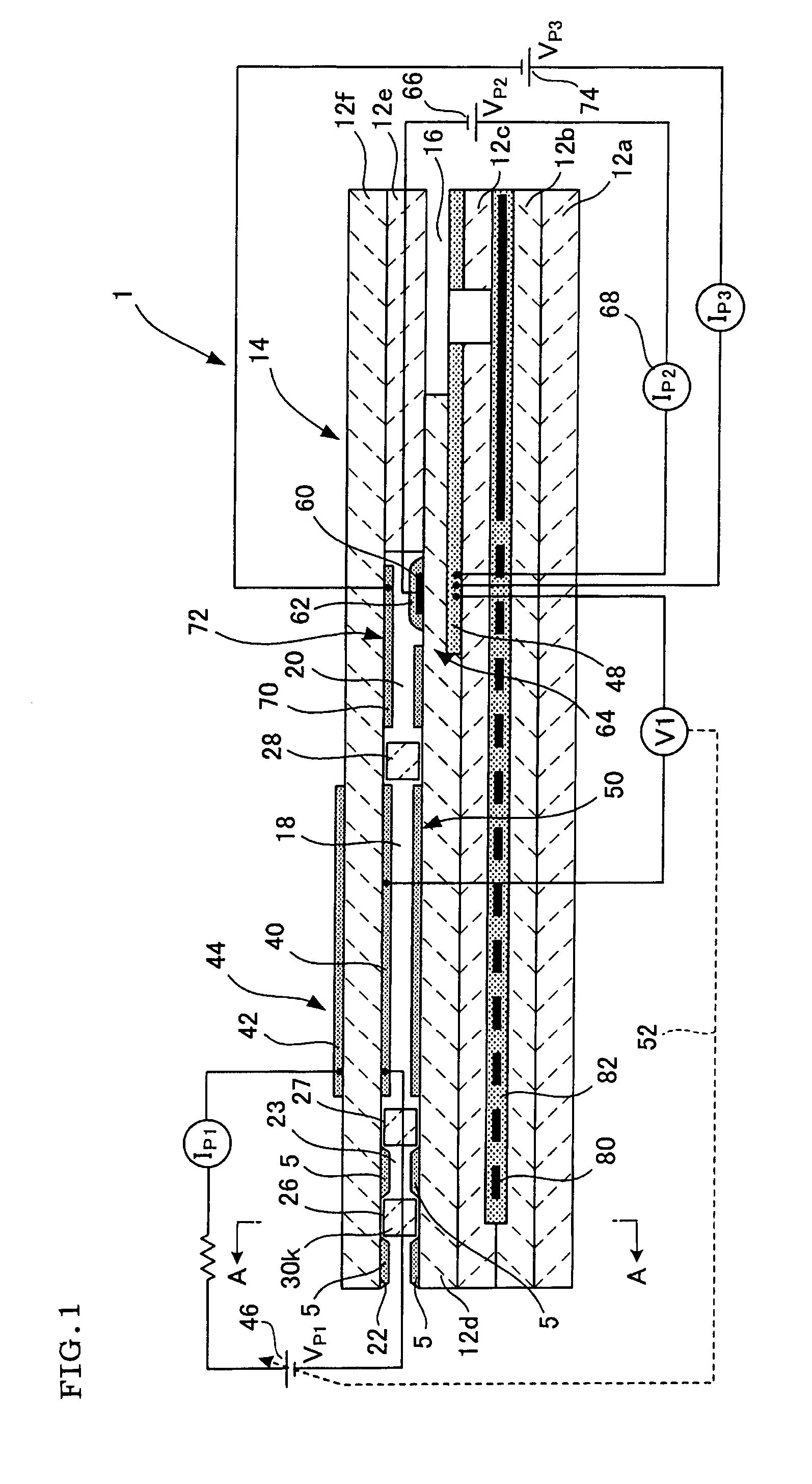
[0042]The gas sensor 1 according to the embodiment 1-1 has, as shown in FIG. 1, a sensor element 14 constituted by six (for example), laminated, solid electrolyte layers 12a to 12f made of a ceramic using an oxygen-conductive solid electrolyte such as ZrO2 or the like.

[0043]In the sensor element 14, the first to third layers from below are a first substrate 12a, a second substrate layer 12b and a third substrate layer 12c, respectively; the fourth and sixth layers from below are a first solid electrolyte layer 12d and a second solid electrolyte layer 12f; and the fifth layer from below is a spacer layer 12e. Between the third substrate layer 12c and the spacer layer 12e, a space 16 for introduction of reference gas, into which a reference gas (e.g. air) used as a reference in oxide measurement is to be introduced, is surrounded and formed by the lower surface of the spacer layer 12e, the upper surface of the third substrate layer 12c and the side of the first solid electrolyte layer...

embodiment 1-2

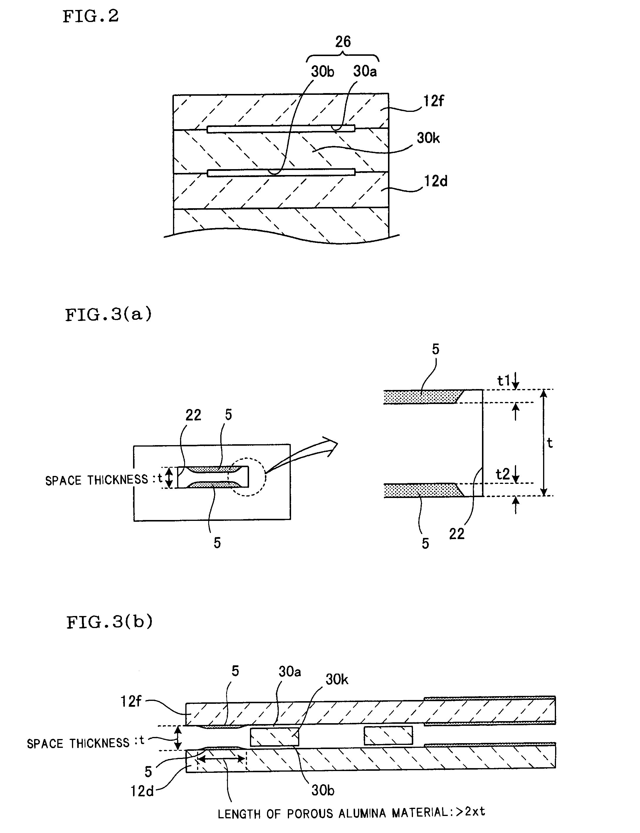
[0086]A gas sensor according to the embodiment 1-2 of the present invention is shown in FIG. 4. In the embodiment 1-2, a first diffusion resistance portion 26, a second diffusion resistance portion 27 and a third diffusion resistance portion 28 are formed as slits, and harmful substance-trapping layers are formed in the gas passage portions formed by the slits 30a and 30b of the diffusion resistance portions 26, 27 and 28.

[0087]In FIG. 5(a) and FIG. 5(b) are shown partially enlarged views for explaining the harmful substance-trapping layers 5 of FIG. 4. As shown in FIG. 5(a), the harmful substance-trapping layers 5 are formed on the walls forming the gas passage portions, specifically on the lower surface of the second solid electrolyte layer 12f and on the upper surface of the first solid electrolyte layer 12d. Or, as shown in FIG. 5(b), the harmful substance-trapping layers 5 may be formed on the upper surface and lower surface of the wall 30k between slits sandwiched by the slits...

embodiment 1-3

[0089]An embodiment 1-3 is shown in FIG. 6. In the embodiment shown in FIG. 6, harmful substance-trapping layers 5 are formed in a gas inlet 22 through which a to-be-measured gas is introduced from an external space into an internal space, and in a buffering space 23 formed between diffusion resistance portions 26 and 27. The harmful substance-trapping layers 5 formed in respective locations are formed by being filled in a gas passage.

[0090]The harmful substance-trapping layers 5 formed by being filled in a gas passage are desirably formed by a porous alumina material having a porosity of 40% to 80%, in order to secure the flow of to-be-measured gas. By forming the harmful substance-trapping layers 5 in this way, the flow amount of to-be-measured gas can be secured, a harmful substance can be trapped, and the to-be-measured gas can be sent to a detection electrode 60 side. Thus, the present embodiment 1-3, when fitted to, for example, the exhaust system of internal combustion engine...


PUM


Abstract

A gas sensor and nitrogen oxide sensor, which, when fitted to the exhaust system of an internal combustion engine, can suppress the influence of harmful substances contained in a measurement gas and can prevent the reduction in sensitivity over time. A harmful substance-trapping layer is formed at a gas inlet for introducing a to-be-measured gas from an external space into an internal space, and in a buffering space formed between diffusion resistance portions. In a trap-formed portion of a gas passage in which the harmful substance-trapping layer is formed, the measurement gas can pass in an amount of 80% or more of when the harmful substance-trapping layer is not formed in the trap-formed portion. A diffusion resistance is attained in the diffusion resistance portions; a harmful substance is trapped in the harmful substance-trapping layer; and the measurement gas is allowed to flow into a detection electrode side.

Description

TECHNICAL FIELD[0001]The present invention relates to a gas sensor for measurement of a particular gas component in a to-be-measured gas and, in particular, to a nitrogen oxide sensor for measurement of NOx as a to-be-measured gas component.BACKGROUND ART[0002]Various measurement methods and measurement apparatuses have been developed in order to know the concentration of a particular gas component in a to-be-measured gas. For example, there is known a gas sensor of limit current type which uses an ion-conductive solid electrolyte. Further, as a method for measurement of NOx in a to-be-measured gas (e.g. a combustion gas), there is known a technique which uses a sensor comprising an oxygen ion-conductive solid electrolyte (e.g. zirconia) and a Pt electrode and a Rh electrode both formed on the solid electrolyte and measures an electromotive force between the two electrodes utilizing the reducing ability of Rh for NOx (for example, Patent Literature 1).[0003]In such a sensor, the ele...

Claims


Application Information

Patent Timeline
IPC IPC(8): G01N27/417
CPCG01N27/419G01N27/4077G01N27/4072G01N27/417
Inventor MIYASHITA, TAKEYALEE, SAN JAENAKAGAKI, KUNIHIKO
Owner NGK INSULATORS LTD
Why Eureka
Try Eureka