Heater, fixing unit and image forming apparatus

a technology of fixing unit and image forming apparatus, which is applied in the direction of electrographic process apparatus, instruments, optics, etc., can solve the problems of surplus power consumption, power consumption of image forming apparatus, and increasing importance of environmental problems, so as to reduce waiting time, improve productivity, and reduce waiting time

Inactive Publication Date: 2009-05-14
RICOH KK
View PDF8 Cites 26 Cited by
  • Summary
  • Abstract
  • Description
  • Claims
  • Application Information

AI Technical Summary

Benefits of technology

[0017]Another and more specific object of the present invention is to provide a heater, a fixing unit and an image forming apparatus, which can improve the utilization efficiency of a capacitor that is used as a secondary battery.
[0033]A further object of the present invention is to provide an image forming apparatus comprising a heater operable with a main power supply unit and a chargeable auxiliary power supplying unit, and comprising a heater part having one or a plurality of heater elements configured to receive power from the main and auxiliary power supplying units; a controller configured to charge the auxiliary power supply unit by the power from the main power supply unit until an output voltage of the auxiliary power supply unit becomes greater than or equal to a target voltage; and a fixing part, heated by the heater part, and configured to fix an image on a recording medium that makes sliding contact with the heater part or pass close to the heater part, the auxiliary power supply unit having a cell capacitance of 500° F. or greater, the target voltage being 80% of a cell rated voltage of the auxiliary power supply unit or greater. According to the image forming apparatus of the present invention, it is possible to reduce the time required to start the image forming apparatus regardless of the power supply state of the main power supply unit, so as to realize a high-speed image forming process, and to simultaneously realize a long serviceable life of the auxiliary power supply unit and a satisfactory image quality of the formed image.

Problems solved by technology

Recently, environmental problems have become increasingly important, and proposals have been made to reduce the power (or energy) consumption of the image forming apparatuses such as copying machines and printers.
But according to this popularly employed method, a certain power must be supplied to the fixing unit even when the fixing unit is not in use, and surplus power is consumed thereby.
It is said that this power consumption in the standby state amounts to approximately 70% to approximately 80% of the total power consumption of devices, units and the like forming the image forming apparatus.
However, if the power consumption of the image forming apparatus in the standby state is set to zero, it will take a long time on the order of several minutes to several tens of minutes to raise the temperature of the heat roller of the fixing unit to the usable temperature of approximately 180° C., because the heat roller is a metal roller mainly made of iron, aluminum or the like having a large heat capacity.
Such a long waiting time required until the temperature of the heat roller reaches the usable temperature will make the image forming apparatus inconvenient to use for the user.
Consequently, the use of the 200 V power supply is not a generally applicable solution for reducing the time required to raise the temperature of the heat roller.
In other words, as long as the commercial power supply of 100 V and 15 A is used, it is difficult to raise the temperature of the heat roller within a short time since a maximum input energy is determined by the power supply.
Consequently, the power consumption cannot be reduced sufficiently.
In addition, making the maximum power supply at the time of starting the normal operating state of the fixing unit higher than the power supplied from the main power supply unit is not the main aim of this proposed method.
The capacity of such secondary batteries deteriorates when repeatedly charged and discharged, and for such secondary batteries, the larger the discharge current the shorter serviceable life.
The capacity of such secondary batteries also deteriorate due to memory effect.
As a result, it becomes necessary to frequently replace the secondary battery, thereby requiring a troublesome operation of replacing the secondary battery, and also increasing the running cost of the image forming apparatus due to the frequently replaced secondary battery.
Furthermore, in the case of the lead battery, it is unsuited for use in office equipments since the lead battery uses sulfuric acid solution as the electrolyte.
In addition, the load on a heater circuit that is built into the heat roller increases, and the making current flows to a peripheral circuit to generate noise, due to a sudden current change, input power and the like when the supply of the large power is started and stopped.
Moreover, when the power from the auxiliary power supply having the large capacity is supplied at once, the excessive supply of power may cause an excessive temperature rise of the heater circuit.
However, no method has conventionally been proposed to judge if the temperature decrease in the fixing unit will be small or zero even when the capacitor is not used.

Method used


Image

  • Heater, fixing unit and image forming apparatus
  • Heater, fixing unit and image forming apparatus
  • Heater, fixing unit and image forming apparatus

Examples


first embodiment

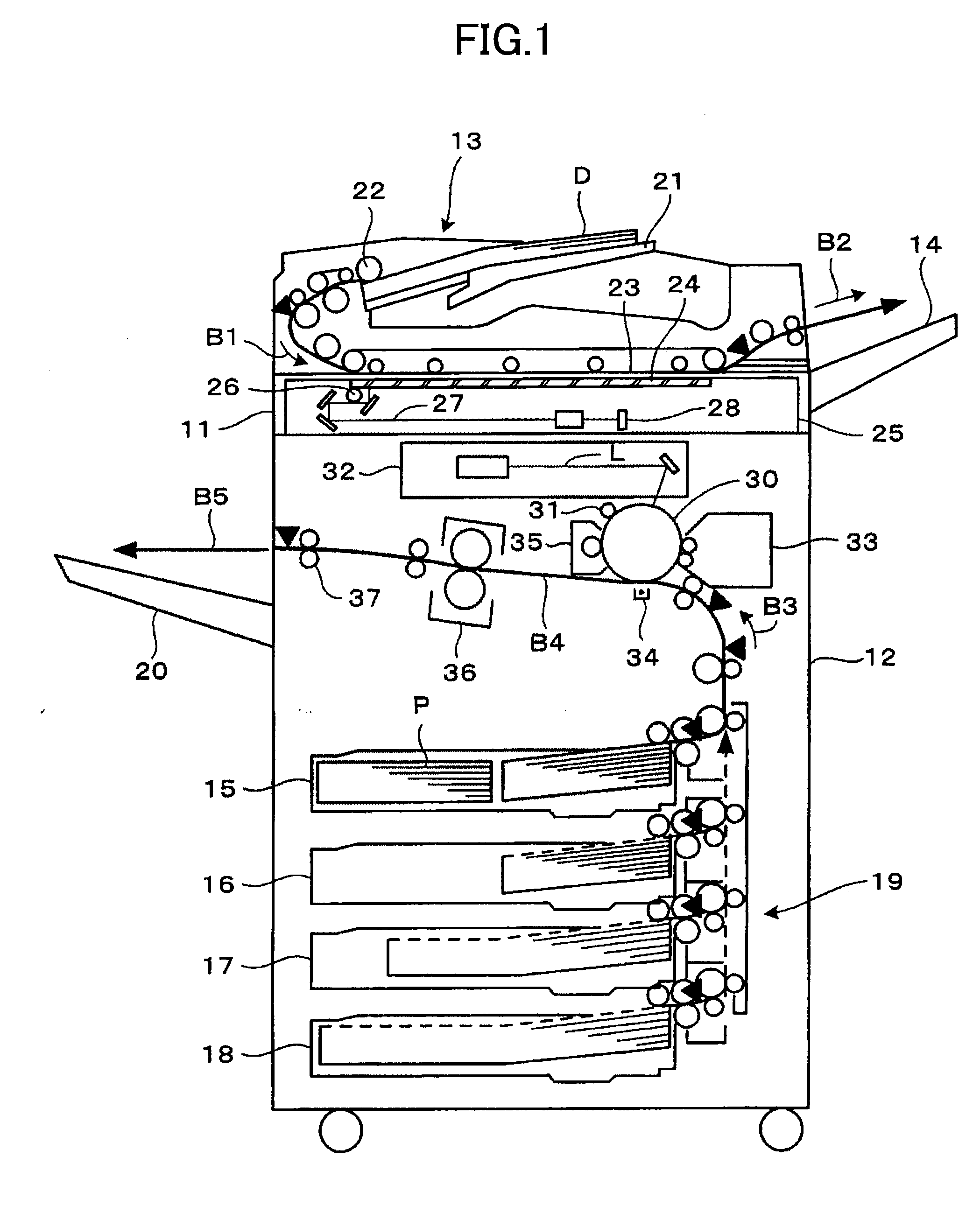
[0079]FIG. 1 is a cross sectional view conceptually showing a first embodiment of an image forming apparatus according to the present invention. In this embodiment, the image forming apparatus includes a document reading unit 11 which reads a document, an image forming unit 12 which forms an image on a recording medium (or recording sheet) P such as paper, an automatic document feeder (ADF) 13, a document eject tray 14 on which documents fed by the ADF 13 are stacked, a media supply unit 19 which is provided with media supply cassettes 15 through 18, and a media eject unit or media eject tray 20 on which recording media P are stacked. In this embodiment of the image forming apparatus, the present invention is applied to a copying machine employing the electrophotography technique. However, the present invention is similarly applicable to other image forming apparatuses such as printers, facsimile machines, and composite apparatuses having at least functions selected from a group con...

seventh modification

of First Embodiment

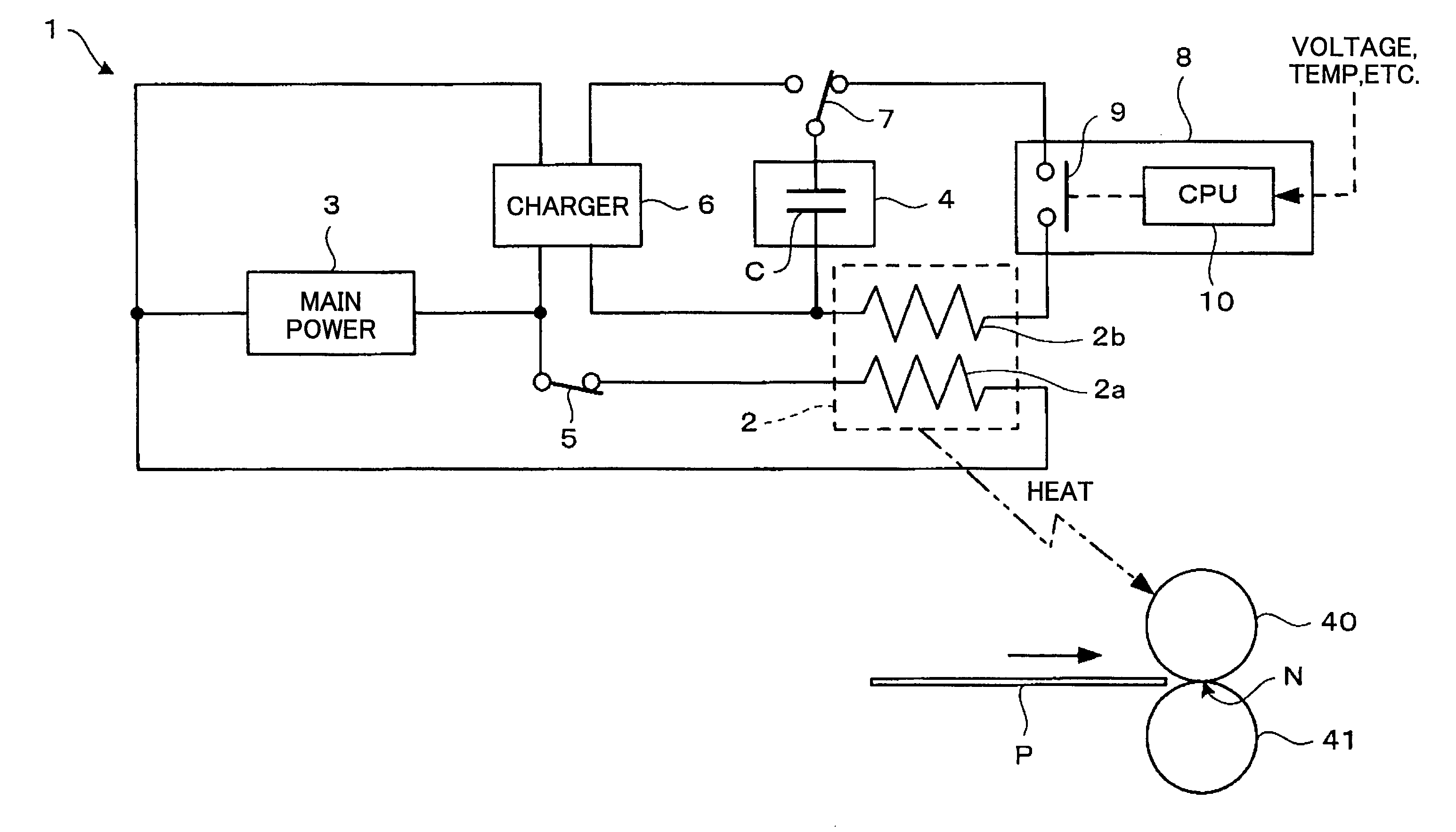
[0129]In a seventh modification of the first embodiment, the work time of a previous job is used for the information that is related to the heater 1 (or heater part 2), as the conditions used to vary the amount of power supplied from the capacitor C. A known timer or time measuring means (not shown) may be used to measure the work time of the previous job. In this case, the controller 8 varies the amount of power supplied from the capacitor C per unit time depending on the work time of the previous job, where the unit time is an arbitrary length of time.

[0130]For example, if the work time of the previous job is longer than a predetermined value, the controller 8 functions as an amount varying unit or means for reducing the amount of power supplied from the auxiliary power supply unit 4 per unit time. In other words, if the work time of the previous job is long, the temperature of the pressure roller 41 remains sufficiently high. In this case, the amount of heat ab...

second embodiment

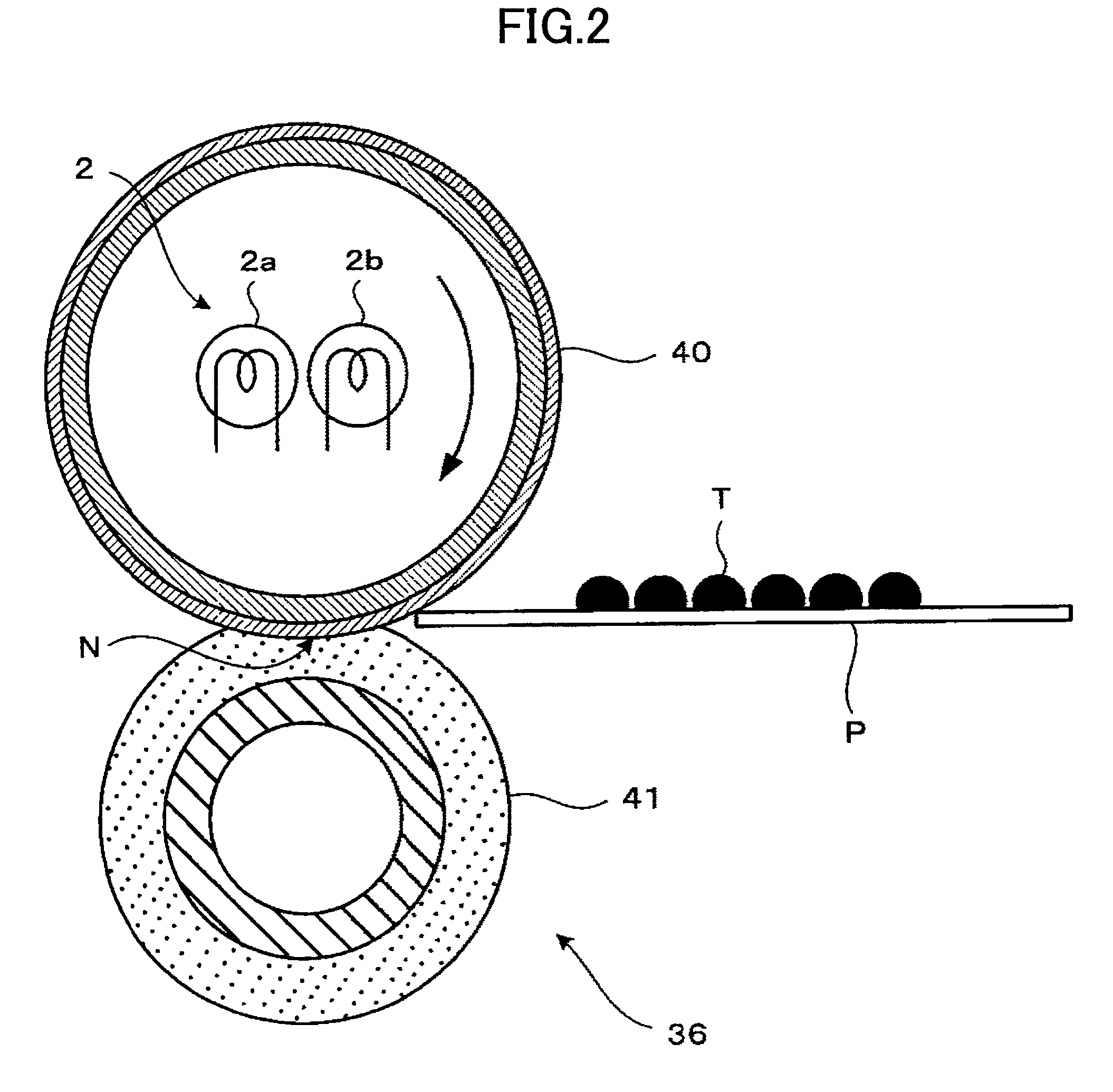
[0137]As described above, the surface temperature of the fixing roller in the standby state needs to be set to a low temperature from the point of view of reducing the power consumption. In addition, from the point of view of reducing the waiting time that is required for the surface temperature of the fixing roller to reach the predetermined fixing temperature from the standby state, it is necessary to reduce the heat capacity of the fixing roller.

[0138]However, compared to the fixing roller having a large heat capacity, the surface temperature of the fixing roller having a small heat capacity drops rapidly when the heat of the fixing roller is absorbed by the recording medium and the toner when fixing the toner image transferred on the recording medium. For this reason, the surface temperature of the fixing roller having the small heat capacity becomes lower than the lower limit of the fixing temperature, and an incomplete fixing easily occurs.

[0139]Hence, in order to prevent the ...


PUM


Abstract

A heater is operable with a main power supply unit and a chargeable auxiliary power supplying unit. The heater includes a heater part having one or a plurality of heater elements to receive power from the main and auxiliary power supplying units, a detecting part to detect information related to the heater part, and a controller to vary an amount of power supplied from the auxiliary power supply unit to the heater part per unit time based on the information detected by the detecting part.

Description

[0001]This application claims the benefit of Japanese Patent Applications No. 2003-408710 filed Dec. 8, 2003, No. 2004-024785 filed Jan. 30, 2004, No. 2004-024794 filed Jan. 30, 2004, and No. 2004-028834 filed Feb. 5, 2004, in the Japanese Patent Office, the disclosures of which are hereby incorporated by reference.BACKGROUND OF THE INVENTION[0002]1. Field of the Invention[0003]The present invention generally relates to heaters, fixing units and image forming apparatuses, and more particularly to a heater that is provided with a capacitor and is used to heat various materials or apparatuses, for example, a fixing unit that uses such a heater, and an image forming apparatus, such as a copying machine, a printer and a facsimile machine, that uses such a fixing unit and employs an electrophotography technique.[0004]2. Description of the Related Art[0005]In an image forming apparatus such as a copying machine, an image is formed on a recording medium that may be plain paper, OHP or the ...

Claims


Application Information

Patent Timeline
Patent Type & Authority Applications(United States)
IPC IPC(8): G03G15/20G03G15/00
CPCG03G15/2003G03G15/5004G03G15/205G03G2215/20G03G15/80
Inventor KISHI, KAZUHITOKATO, YASUHISAOKAMOTO, MASAMITSUKIOKA, YASUTADATAKAGI, HIROMASAMATSUSAKA, SUSUMUAMITA, AKIYASU
Owner RICOH KK
Why Eureka
Try Eureka