
Method and apparatus of driving multiple shafts in a wet/dry vacuum and liquid pump

Inactive Publication Date: 2009-05-14
EMERSON ELECTRIC CO
View PDF22 Cites 15 Cited by
  • Summary
  • Abstract
  • Description
  • Claims
  • Application Information

AI Technical Summary

Benefits of technology

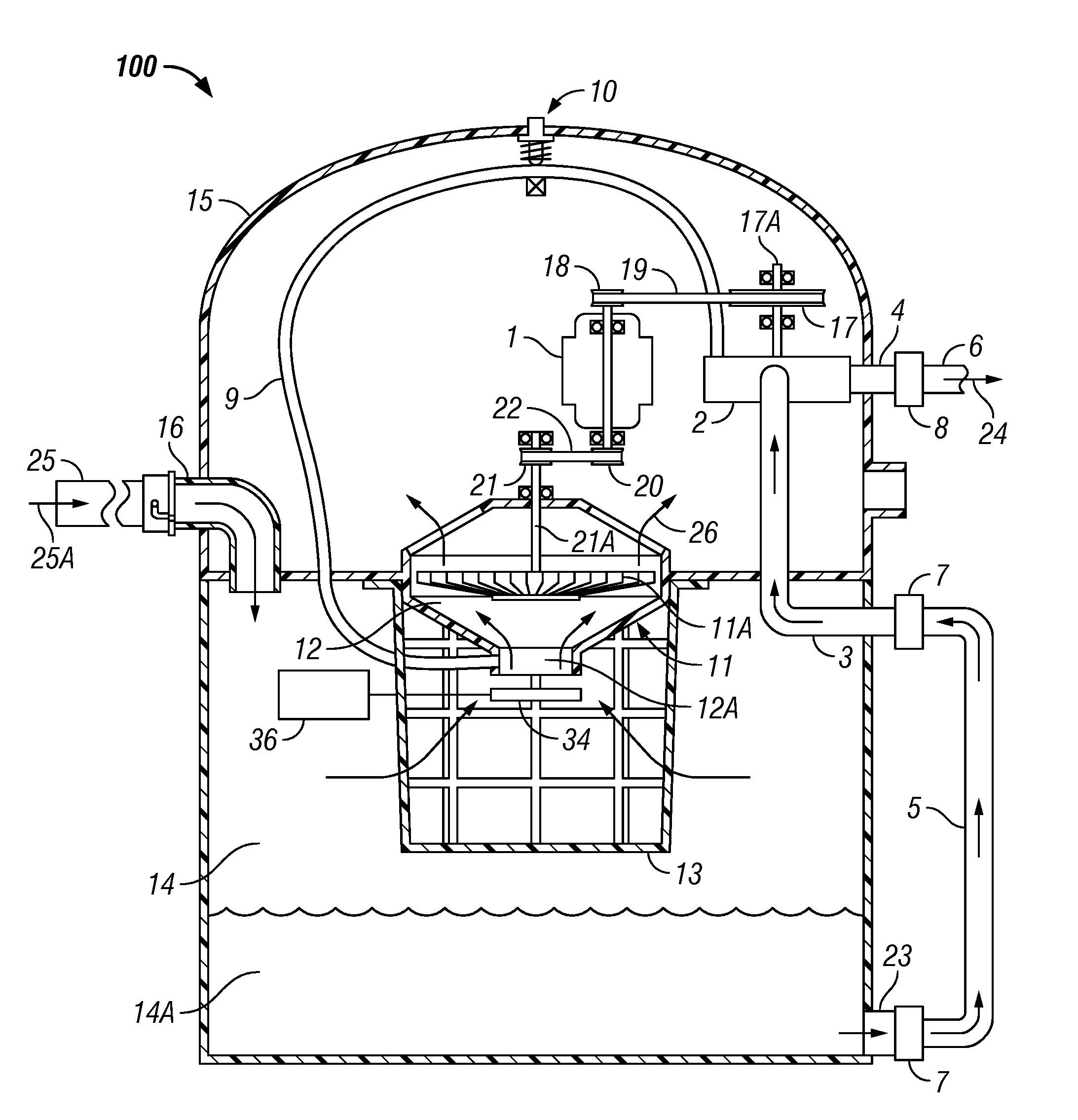
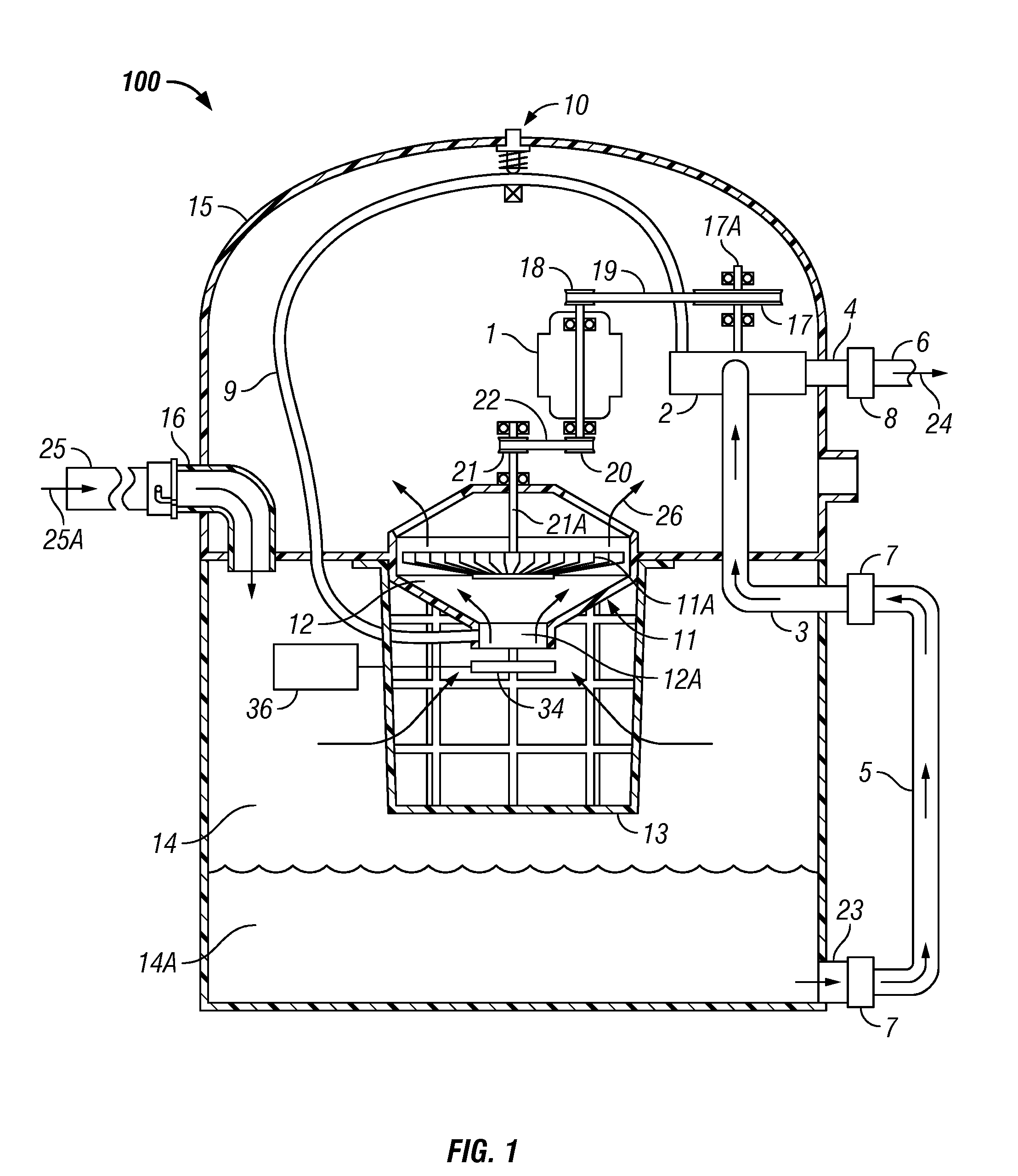
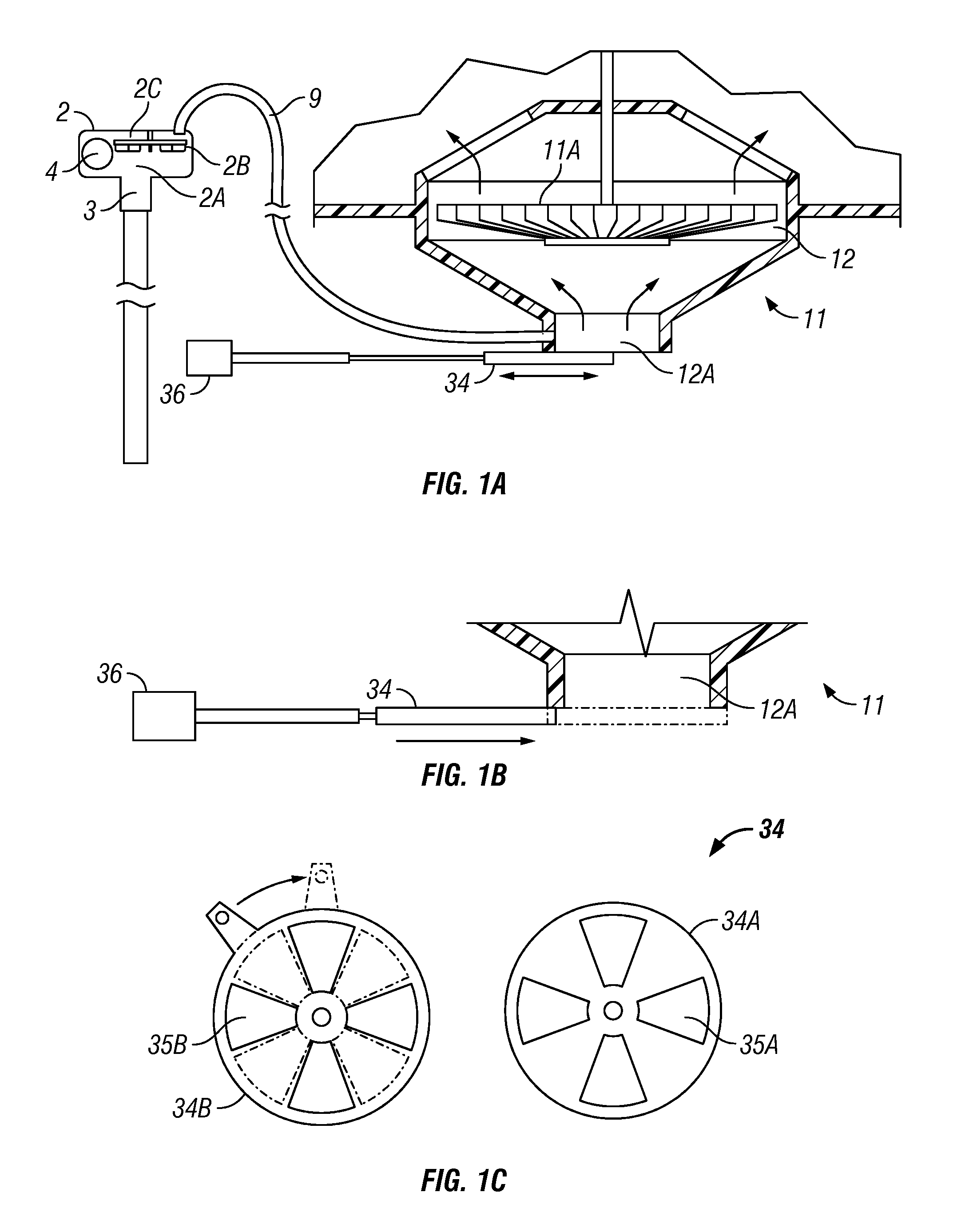
[0013]The present disclosure provides a method and system to supply pumping capabilities to a wet and dry vacuum cleaner. A single motor can operate a vacuum unit and the pump distinct from the vacuum unit. A port in the vacuum flow path can act as a vacuum tap to prime the pump when necessary. The pump can be arranged so it pumps fluids out of the drum or can directly pump the fluids without having to flow first into the drum container of the vacuum cleaner. The system can allow independent operation of the vacuum unit and the pump, and allow different, more efficient speeds for each, which allows a higher overall performance, since maximum power for the system can be provided to either operating device while the other one is not operating. Accordingly, the disclosure further provides a system and method for separately engaging and disengaging the vacuum unit and the pump. In at least one embodiment, the various engagements of the pulleys with their respective belts and shafts can be controlled by clutches and other known drive systems to selectively operate in the different modes described herein.

Problems solved by technology

However, many locations, such as in a basement, do not facilitate easy draining.
The arrangement makes the disassembly and maintenance of the vacuum somewhat more complicated and the flow paths are problematic.
Mounting the pump above the water line such as in the lid at the top of the vacuum cleaner with the vacuum motor can also be problematic.

Method used


Image

  • Method and apparatus of driving multiple shafts in a wet/dry vacuum and liquid pump
  • Method and apparatus of driving multiple shafts in a wet/dry vacuum and liquid pump
  • Method and apparatus of driving multiple shafts in a wet/dry vacuum and liquid pump

Examples


Embodiment Construction

[0032]One or more illustrative embodiments incorporating the invention disclosed herein are presented below. Not all features of an actual implementation are described or shown in this application for the sake of clarity. It is understood that in the development of an actual embodiment incorporating the present invention, numerous implementation-specific decisions must be made to achieve the developer's goals, such as compliance with system-related, business-related and other constraints, which vary by implementation and from time to time. While a developer's efforts might be complex and time-consuming, such efforts would be, nevertheless, a routine undertaking for those of ordinary skill in the art having benefit of this disclosure.

[0033]In general, the disclosure provides a combined vacuum and pump system that can vacuum, pump, or a combination thereof by switching between different operational modes. Specifically, the mechanical switching control mechanism (or equivalent electric...


PUM


Abstract

The present disclosure provides a method and system to supply pumping capabilities to a wet and dry vacuum cleaner. A single motor can operate a vacuum unit and the pump distinct from the vacuum unit. A port in the vacuum flow path can act as a vacuum tap to prime the pump when necessary. The pump can directly pump the fluids without having to flow first into the drum container of the vacuum cleaner. The system can allow independent operation of the vacuum unit and the pump and at different, more optimal speeds for each, allowing a higher performance on each of the vacuum unit and the pump, since maximum power for the system can be provided to either the operating device while the other one is not operating. Accordingly, the disclosure further provides a system and method for separately engaging and disengaging the vacuum unit and the pump.

Description

CROSS REFERENCE TO RELATED APPLICATIONS[0001]Not applicable.STATEMENT REGARDING FEDERALLY SPONSORED RESEARCH OR DEVELOPMENT[0002]Not applicable.NAMES OF PARTIES TO A JOINT RESEARCH AGREEMENT[0003]Not applicable.REFERENCE TO APPENDIX[0004]Not applicable.BACKGROUND[0005]1. Field of the Invention[0006]The invention relates to wet and dry vacuums. More specifically, the invention relates to wet and dry vacuums capable of pumping liquids.[0007]2. Description of Related Art[0008]Well known wet and dry vacuum cleaners can vacuum wet or dry materials into a container. Typically, a suction system with a motor creates a vacuum of pressure less than ambient pressure and is mounted in a lid that is removably attached to a collection drum for receiving the vacuumed materials. A portion of the lid extends downward into the drum and mounts a filter support assembly, such as commonly known as a “cage,” that covers a vacuum intake to the suction assembly in the lid. The suction system in the lid suc...

Claims


Application Information

Patent Timeline
IPC IPC(8): F04B49/08
CPCA47L5/22A47L7/0028A47L9/22A47L9/106A47L7/0038F04D9/04
Inventor GIERER, JOSEPH T.MARTIN, MICHAEL F.BETH, DAVID E.YOUNG, JEFFREY L.
Owner EMERSON ELECTRIC CO
Learn More