Method for monitoring the quality of crop material

a crop material and quality technology, applied in the field of crop material quality monitoring, can solve the problems of grain loss, interference with the further processing of grain, negative effect of durability of grain, etc., and achieve the effect of reducing background noise and unnecessary loss of crop material

Active Publication Date: 2009-05-14
CLAAS SELBSTFAHRENDE ERNTEMASCHINEN GMBH
View PDF12 Cites 30 Cited by
  • Summary
  • Abstract
  • Description
  • Claims
  • Application Information

AI Technical Summary

Benefits of technology

[0011]The object of the present invention is to eliminate the disadvantages of the related art and, in particular, to provide a method with lower background noise for evaluating the crop-material quality which enables the producer to ensure a desired level of quality of the crop material without excessively acute settings of his harvesting machine resulting in unnecessary losses of crop material.

Problems solved by technology

With a combine harvester, for instance, when the threshing mechanism setting is too acute, a high percentage of damaged grain results, which is undesired, because this has a negative effect on the durability of the grain.
If the setting is too gentle, grains that have not been fully threshed enter the crop material, and this interferes with the further processing of the grain.
Husks and short straw that enter the crop-material flow during threshing may indeed be removed in a wind separator located downstream of a threshing stage, although a setting of the wind separator that is too acute may also result in grain losses.
The conventional method that the operator of the machine uses to evaluate the crop-material quality is not entirely objective, however, and the efficacy of the method depends greatly on the amount of attention that the operator is able to devote to managing the crop-material quality.
Since the method is incapable of distinguishing between the image of an unattached, well-illuminated but dark object and an image of an object that is light per se but that is located in the shadow of other objects, a measurement performed using this method unavoidably contains a significant background signal.

Method used


Image

  • Method for monitoring the quality of crop material
  • Method for monitoring the quality of crop material
  • Method for monitoring the quality of crop material

Examples


Embodiment Construction

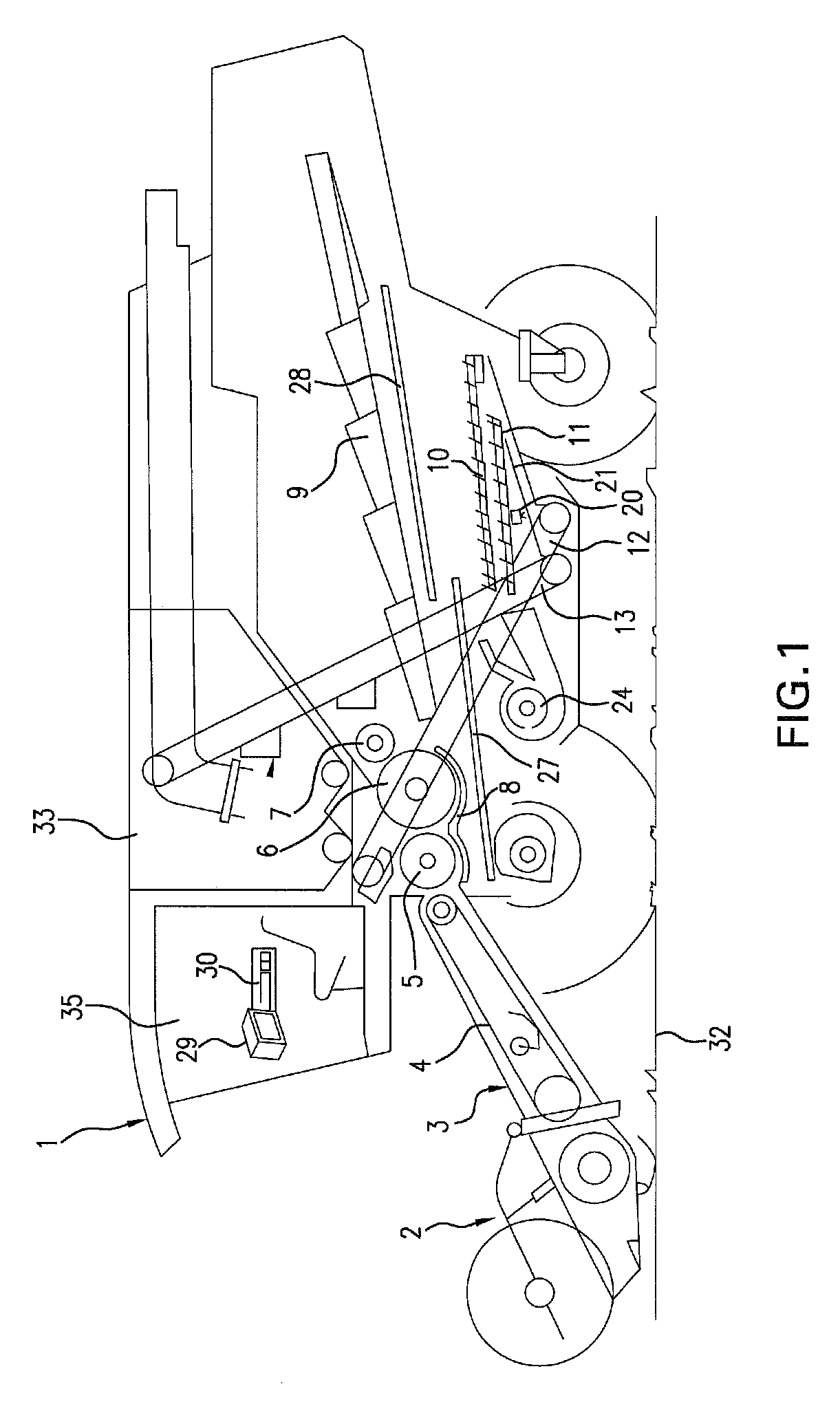
[0036]FIG. 1 shows a schematic side view of a combine harvester 1. A grain-cutting device 2 is used to cut and pick up grain stalks from a field 32 and to convey them to a feeder 3. Rotating feed chains 4 are located inside feeder 3. Feed chains 4 include cross braces that convey the crop material to downstream threshing units 5, 6. The crop material is removed by a preacceleration cylinder 5 at the end of feeder 3 and is accelerated around the circumference of preacceleration cylinder 5 between preacceleration cylinder 5 and a concave 8. The accelerated crop material is transferred to cylinder 6 and is accelerated further. The crop material is separated from the ears and straw via the striking and rubbing effect of preacceleration cylinder 5 and cylinder 6, and via the centrifugal force acting on the crop material. The crop material then travels through concave 8, which allows the crop material to pass, and reaches grain pan 27. The straw output by cylinder 6 is redirected via impe...


PUM


Abstract

A method for estimating a portion of undesired particles in crop material includes taking a photograph of the crop material; identifying images of at least one type of undesired particle in the photograph that was taken; measuring the surface area covered by the image of every particle shown in the photograph; and determining the portion of undesired particles as a proportion of the surface area of the images, and may be used, in particular, in a harvesting machine on the crop material picked up in an on-going harvesting operation.

Description

CROSS-REFERENCE TO RELATED APPLICATION[0001]The invention described and claimed hereinbelow is also described in German Patent Application DE 10 2007 053 662.5 filed on Nov. 10, 2007. This German Patent Application, whose subject matter is incorporated here by reference, provides the basis for a claim of priority of invention under 35 U.S.C. 119(a)-(d).BACKGROUND OF THE INVENTION[0002]The present invention relates to a method for estimating the portion of undesired particles in crop material.[0003]The quality, in particular the purity of a crop material such as grain, is a decisive factor in determining the type of further processing to carry out, and is therefore also a decisive factor for the price that the farmer may obtain for the crop material. The purchaser of the crop material generally defines limiting values for the portion of undesired particles in the crop material, that is, the purchase price drops if the portion of undesired particles in the crop material exceeds these ...

Claims


Application Information

Patent Timeline
Patent Type & Authority Applications(United States)
IPC IPC(8): G06F7/00G06K9/00
CPCA01D41/1277A01D41/127
Inventor BEHNKE, WILLI
Owner CLAAS SELBSTFAHRENDE ERNTEMASCHINEN GMBH
Why Eureka
Try Eureka