
Arm connection for a structural member

Active Publication Date: 2009-05-21
MEYER UTILITY STRUCTURES LLC
View PDF8 Cites 6 Cited by
  • Summary
  • Abstract
  • Description
  • Claims
  • Application Information

AI Technical Summary

Benefits of technology

[0006]At least one cross brace is joined between the first thru-vang and the second thru-vang for structural support. Preferably two cross braces are used and positioned such that they are spaced away from the structural member to allow for easier welding of the thru-vangs and / or the cross braces. Alternatively, a plurality of conduits are joined between each of the plurality of apertures of the first thru-vang and the second thru-vang for structural support and to aid in insertion of the plurality of pins. The plurality of conduits may be at least partially threaded to receive a threaded bolt or rod therein.

Problems solved by technology

The arms are also typically long and heavy since they must support the weight of multiple electrical conductors at all times and especially during storms.
Ice can also build up on the conductors and add even more weight to the conductors and arms.
The numerous bolts are so large (typically 1.5 inches or greater in diameter), the abutting thru-vangs and arm brackets so thick (typically 2 inches or more) that the connection of the arm to the thru-vangs is time consuming and requires great force.
The odd size of the bolts makes them difficult to purchase on the open market if one is lost.
What's more, the number of bolts required for a secure arm connection takes a considerable amount of time.
Last, there may be insufficient clearance for the torquing wrenches to be received inside the bracket, further delaying securement of the arms.

Method used


Image

  • Arm connection for a structural member
  • Arm connection for a structural member
  • Arm connection for a structural member

Examples


Embodiment Construction

)

[0022]The above and other features, aspects, and advantages of the present invention will now be discussed in the following detailed description of preferred embodiments and appended claims, which are to be considered in conjunction with the accompanying drawings in which identical reference characters designate like elements throughout the views.

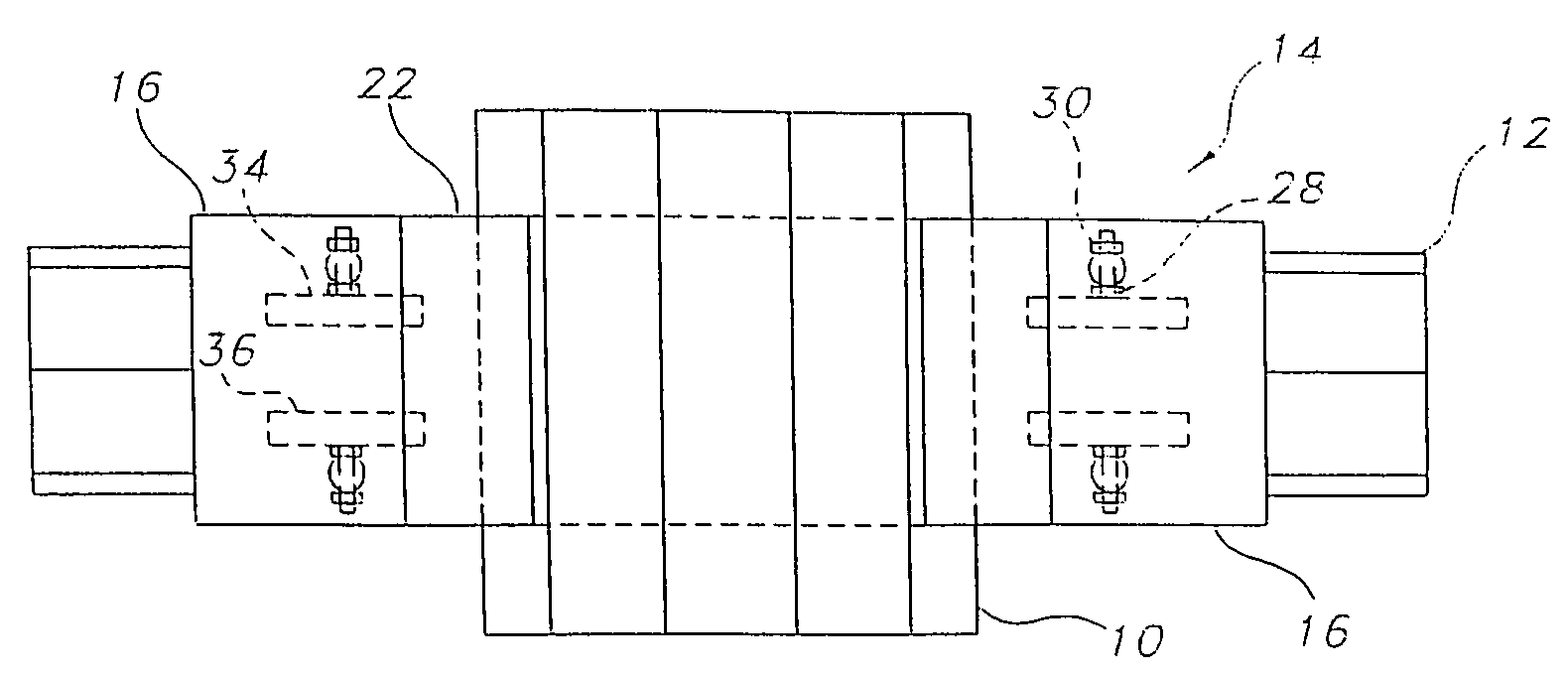
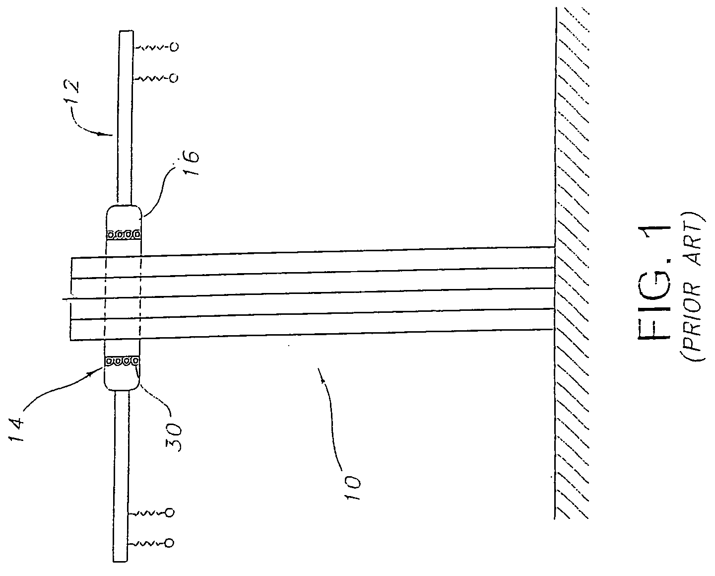
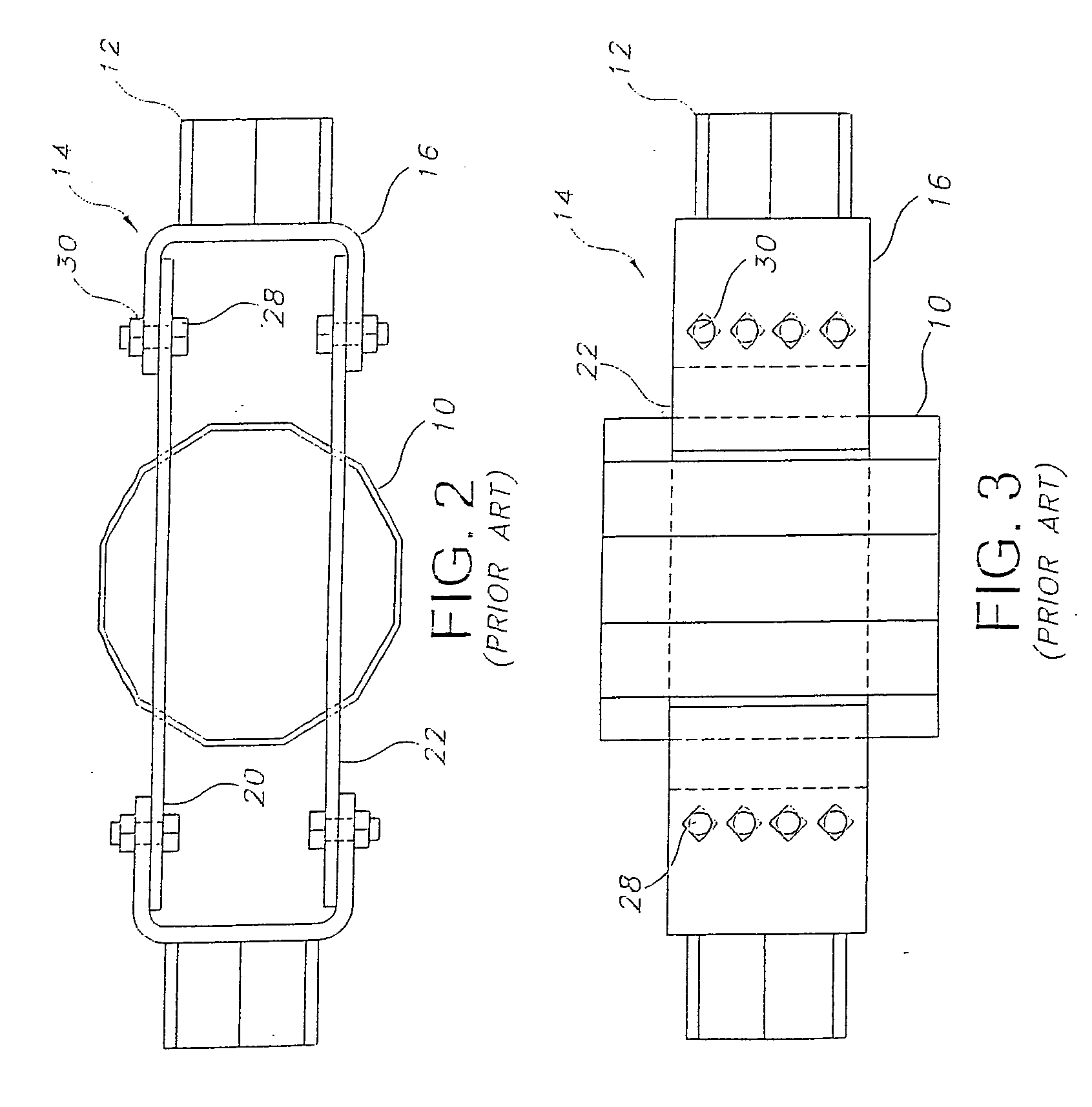
[0023]Shown in FIG. 1 is a typical structural member 10 that is used in the electrical transmission industry to suspend electrical conductors above the ground via arms 12 that are welded to an arm bracket 16, which is secured to the structural member 10. More particularly, as shown in FIGS. 2 and 3, the arm bracket 16 is secured to the structural member 10 at arm connection 14. During field installation of the arms 12, the arm bracket 16 is positioned such that it abuts a first thru-vang 20 and a second thru-vang 22 and they are bolted together. This is accomplished by the use of typically sixteen threaded bolt 28 and nut 30 combinations t...


PUM


Abstract

A structural member and method with an improved arm connection is provided that allows quick connection of an arm to the structural member. Bolts are inserted through aligned apertures in first and second thru-vangs, as well as an abutting arm bracket. A securement member is inserted through an aperture in the bolts that is transverse to the bolts. Last, an arm is secured to the arm bracket for support of electrical conductors strung thereon.

Description

RELATED REFERENCE[0001]This is a Continuation-in-Part of co-pending U.S. application Ser. No. 11 / 655,355 filed Jan. 19, 2007.FIELD OF THE INVENTION[0002]In general, the present invention relates to structural members. More particularly, the present invention relates to improved arm connections for structural members such as electrical transmission and distribution poles that support electrical conductors above ground.BACKGROUND[0003]Structural members such as electrical transmission poles have been used for decades to run electrical conductor high above the ground to span great distances. The method has proven less costly and less time consuming than running electrical conductors underground where numerous obstructions are encountered and rights of way needed. Arms are connected to the structural members to hold the electrical conductors away from the structural member high above the ground. The arms are also typically long and heavy since they must support the weight of multiple el...

Claims


Application Information

Patent Timeline
IPC IPC(8): E04H12/00
CPCE04H12/24
Inventor NAHLEN, DAVID J.GALL, MICHAEL R.
Owner MEYER UTILITY STRUCTURES LLC
Features
  • Generate Ideas
  • Intellectual Property
  • Life Sciences
  • Materials
  • Tech Scout
  • Unparalleled Data Quality
  • Higher Quality Content
  • 60% Fewer Hallucinations
Learn More