
Differential Limiting Control Apparatus For Four-Wheel Drive Vehicle

a four-wheel drive vehicle and limiting control technology, applied in the direction of control devices, driver input parameters, vehicle components, etc., can solve the problems of reducing and deficiency of the limiting force, so as to improve the turning performance of the vehicle

Active Publication Date: 2009-05-21
MITSUBISHI MOTORS CORP
View PDF10 Cites 30 Cited by
  • Summary
  • Abstract
  • Description
  • Claims
  • Application Information

AI Technical Summary

Benefits of technology

[0007]The present invention was made to solve the above problem, and an object thereof is to provide a differential limiting control apparatus for a four-wheel drive vehicle which is capable of restraining under-steering attributable to differential limiting between front and rear wheels when the rotational speed difference between right and left wheels increases due to slipping, thereby maintaining satisfactory turning performance of the vehicle.
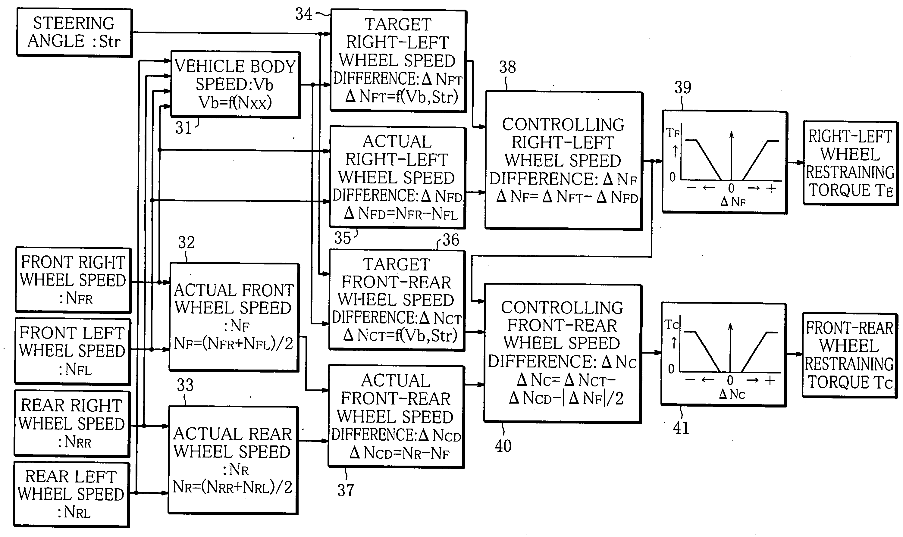
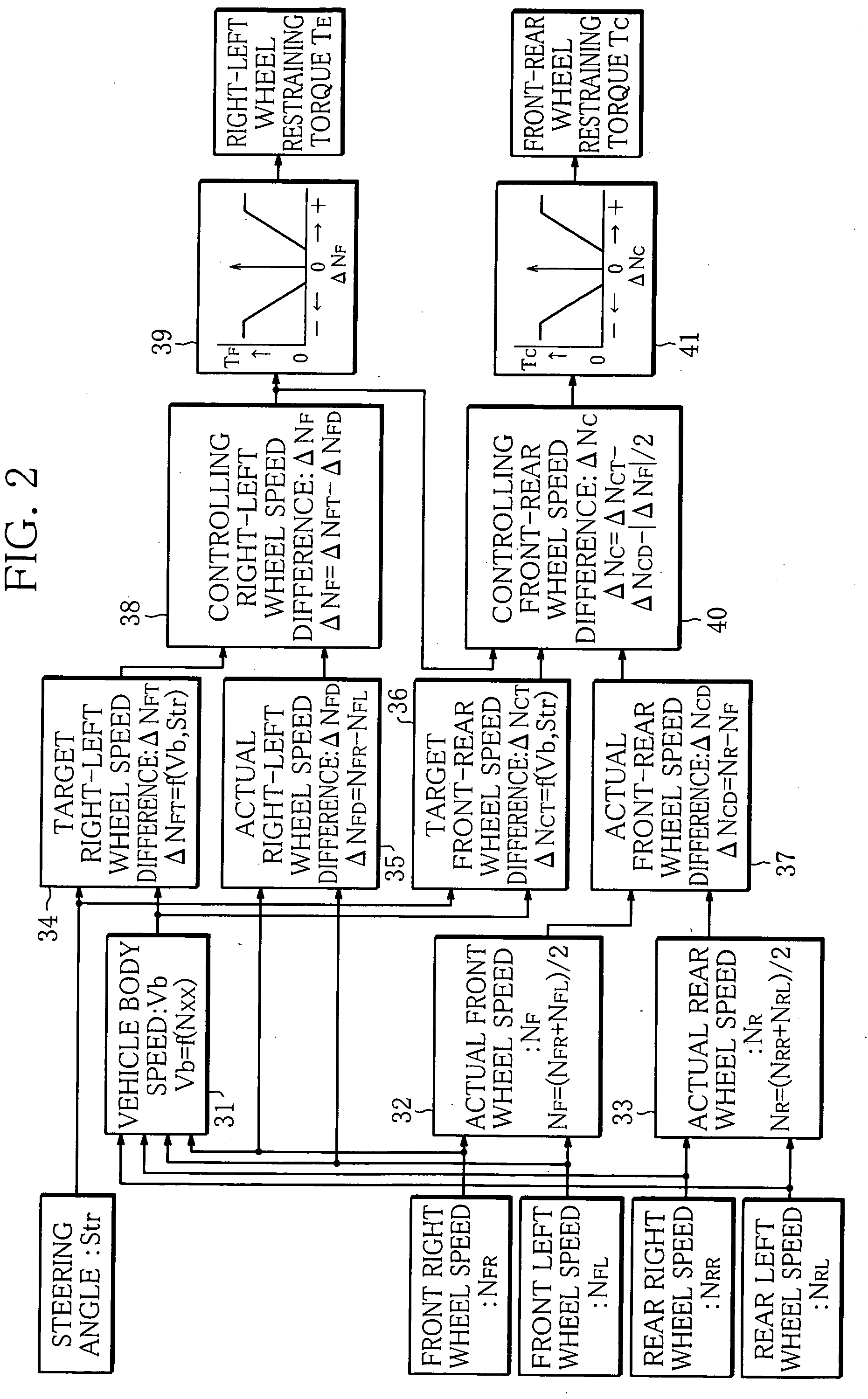
[0009]Thus, the rotational speed difference between the front and rear wheels is corrected so as to decrease in accordance with the rotational speed difference between the right and left front wheels or rear wheels to which the motive power of the engine is transmitted at all times, and on the basis of the corrected rotational speed difference, the differential limiting force of the front-rear wheel differential limiting mechanism is controlled by the front-rear wheel differential limiting control means. In a vehicle in which the motive power of the engine is transmitted at all times to the front wheels, for example, if the inner front wheel starts to slip as a result of turning, the average wheel speed of the right and left front wheels becomes higher than that of the right and left rear wheels. With the differential limiting control apparatus of the present invention, the rotational speed difference between the front and rear wheels is corrected so as to decrease in accordance with the rotational speed difference between the right and left front wheels. It is therefore possible to avoid a situation where the differential limiting between the front and rear wheels is intensified due to the rotational speed difference between the right and left front wheels, thus restraining under-steering from being furthered by the differential limiting between the front and rear wheels.
[0010]In this manner, the differential limiting control apparatus of the present invention prevents the differential limiting between the front and rear wheels from being intensified when the rotational speed difference between the right and left wheels to which the motive power of the engine is transmitted at all times increases due to slipping, whereby under-steering attributable to the differential limiting between the front and rear wheels is restrained, making it possible to maintain satisfactory turning performance of the vehicle.
[0013]In this manner, the rotational speed difference between the front and rear wheels is corrected so as to decrease in accordance with the difference between the target turning rotational difference and the actual rotational speed difference, whereby the differential limiting between the front and rear wheels can be executed more appropriately without being influenced by turning of the vehicle.
[0015]Where a rotational speed difference occurs between the right and left wheels due to slipping, the rotational speed difference between the front and rear wheels increases by ½ of the rotational speed difference occurring between the right and left wheels. Taking the phenomenon into account, in the differential limiting control apparatus of the present invention, ½ of the rotational speed difference between the right and left wheels is subtracted from the rotational speed difference between the front and rear wheels, and this makes it possible to substantially perfectly eliminate the influence of the rotational speed difference caused between the right and left wheels due to slipping. Consequently, under-steering attributable to the differential limiting between the front and rear wheels can be restrained without fail.
[0017]Thus, since the differential limiting force of the right-left wheel differential limiting mechanism is controlled in accordance with the rotational speed difference between the right and left wheels, the differential limiting between the right and left wheels can be optimized at all times. As a result, not only the differential limiting between the front and rear wheels but also the differential limiting between the right and left wheels can be properly executed, making it possible to further improve the turning performance of the vehicle.

Problems solved by technology

Where slipping of one of the four wheels is restrained by means of the differential limiting force applied between the front and rear wheels, the differential limiting force tends to be deficient because the rotational speed difference between the front and rear wheels is ½ that between the right and left wheels caused by the slipping.
However, in situations where the inner front wheel is slipping, the average wheel speed of the right and left front wheels is higher than that of the right and left rear wheels because of the slipping of the inner wheel, and therefore, not only the differential limiting between the right and left wheels but also the differential limiting based on the rotational speed difference between the front and rear wheels are executed.
Consequently, the differential limiting between the front and rear wheels hinders turning of the vehicle and furthers under-steering, giving rise to the problem that the turning performance of the vehicle lowers.
Increasing the differential limiting force, however, furthers under-steering and lowers turning performance, with the result that the problem remains unsolved.

Method used


Image

  • Differential Limiting Control Apparatus For Four-Wheel Drive Vehicle
  • Differential Limiting Control Apparatus For Four-Wheel Drive Vehicle
  • Differential Limiting Control Apparatus For Four-Wheel Drive Vehicle

Examples


Embodiment Construction

[0021]The present invention will be hereinafter described in detail, wherein the invention is embodied as a differential limiting control apparatus for an electronic control type on-demand four-wheel drive vehicle with an FF layout (front-engine and front drive layout).

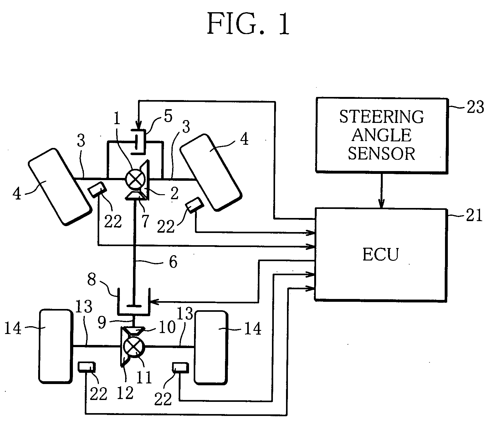
[0022]FIG. 1 shows an entire arrangement of the differential limiting control apparatus for a four-wheel drive vehicle according to the embodiment. A front differential 1 is arranged between right and left front wheels 4 of the vehicle. A ring gear 2 is fixed to the front differential 1 and is input with motive power from an engine through a transmission, neither is shown. The front differential 1 is coupled through drive shafts 3 to the right and left front wheels 4, respectively, and transmits the motive power of the engine, input to the ring gear 2, to the right and left front wheels 4 while allowing differential action. An electronic controlled front limited slip differential 5 (right-left wheel differential limit...


PUM


Abstract

Restraining torque TF of an electronic controlled front limited slip differential (5) arranged between right and left front wheels is controlled in accordance with controlling right-left wheel rotational speed difference ΔNF, which is the rotational speed difference between the right and left front wheels, while restraining torque TC of an electronic controlled coupling (8) arranged between the front and rear wheels is controlled in accordance with controlling front-rear wheel rotational speed difference ΔNC obtained by subtracting ½ of the rotational speed difference between the right and left wheels (|ΔNF| / 2) from the rotational speed difference (ΔNCT−ΔNCD) between the front and rear wheels.

Description

TECHNICAL FIELD[0001]The present invention relates to a differential limiting control apparatus for controlling differential limiting force applied between right and left wheels and between front and rear wheels of a four-wheel drive vehicle.BACKGROUND ART[0002]As four-wheel drive vehicles, there have been known an on-demand four-wheel drive vehicle in which motive power from the engine is transmitted at all times to either the front wheels or the rear wheels and, when necessary, part of the motive power is transmitted also to the other of the front wheels and the rear wheels, and a full-time four-wheel drive vehicle in which the driving force is transmitted to the four wheels at all times. In some four-wheel drive vehicles, an electronic controlled differential limiting device is provided between the right and left wheels or between the front and rear wheels. The differential limiting device applies a suitable differential limiting force between the right and left wheels or between...

Claims


Application Information

Patent Timeline
IPC IPC(8): B60K17/35
CPCB60K28/165B60W10/02B60W10/119B60W2520/28B60W30/045B60W2520/10B60W2520/263B60W10/16B60W2540/18
Inventor USHIRODA, YUICHISAWASE, KAORUFUJII, YUSUKE
Owner MITSUBISHI MOTORS CORP
Learn More