Flat panel detector with temperature sensor

Inactive Publication Date: 2009-05-21
SIEMENS AG
View PDF8 Cites 6 Cited by
  • Summary
  • Abstract
  • Description
  • Claims
  • Application Information

AI Technical Summary

Benefits of technology

[0009]An object of the invention is to provide a flat pa

Problems solved by technology

Thermal influences can disruptively affect the image acquisition both in indirect and direct flat panel detectors.
The local temperature differences created

Method used


Image

  • Flat panel detector with temperature sensor
  • Flat panel detector with temperature sensor
  • Flat panel detector with temperature sensor

Examples


Embodiment Construction

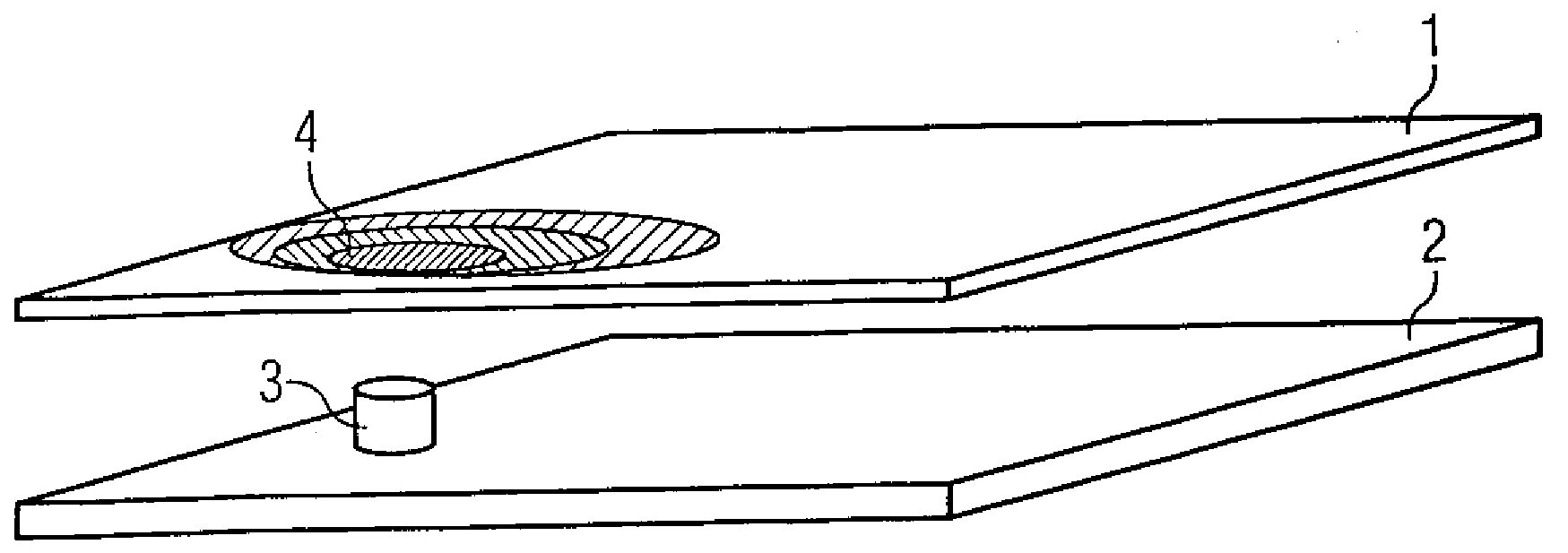
[0031]FIG. 1 shows a flat panel detector 1 in the form of a plate. Arranged below is a circuit board 2, for example an analog board with electronic modules (not presented in detail). The flat panel detector 1 is locally heated in the region 4 (identified in FIG. 1) by a heat-emitting module 3. Spatially different temperature distributions result on the flat panel detector, which can lead to different dark currents, electrical noise and an increase of the ghost image response. The image quality of an x-ray image exposure thereby degrades. Measures to detect the temperature distribution are required for prevention.

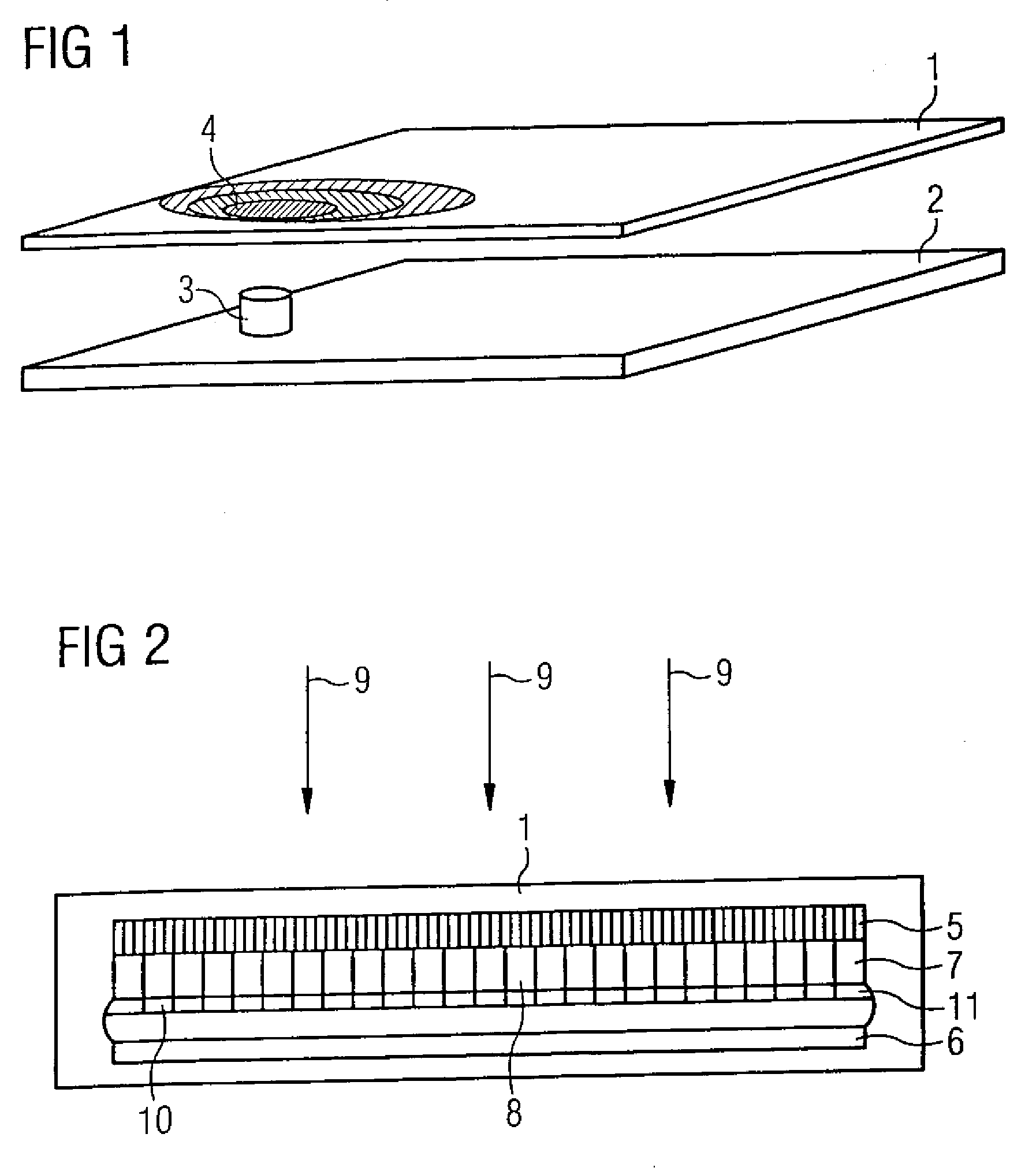
[0032]FIG. 2 shows a flat panel detector according to the invention which contains: a scintillator layer 5 as an indirect converter of an incident x-ray radiation 9; an evaluation electronic 6; and an active matrix (what is known as a radiation sensor 7) composed of a number of radiation sensor elements 8 arranged in a matrix. The radiation sensor elements 8 respectively con...


PUM


Abstract

A flat panel detector for x-ray radiation has at least one radiation sensor and at least one temperature sensor. The radiation sensor is composed of a number of radiation sensor elements. The temperature sensor is of laminar design, and its surface is approximately equal in size to the surface of the radiation sensor. The temperature sensor can be formed by a number of temperature sensor elements. The current temperature of each pixel of the radiation sensor thus can be determined.

Description

BACKGROUND OF THE INVENTION[0001]1. Field of the Invention[0002]The invention concerns a flat panel detector for x-ray radiation.[0003]2. Description of the Prior Art[0004]In modern x-ray imaging, flat panel detectors (also called solid state detectors) are known that directly deliver an x-ray image in digital form. Two types of flat panel detectors are differentiated: indirect and direct.[0005]In an indirect flat panel detector, the incident x-ray radiation is converted by means of a scintillator into visible light. A semiconductor (normally made of amorphous silicon) from which an integrated circuit for transduction of the visible light into electrical signals is formed is located below the scintillator. There is one capacitor, one thin film transistor (also called a TFT) and one photodiode per pixel. The photodiode transduces the visible light into electrons. The capacitor stores this charge, and the pixel can be read out with the aid of the thin film transistor.[0006]Instead of ...

Claims


Application Information

Patent Timeline
IPC IPC(8): G01T1/24G01K3/00
CPCG01T1/2018G01T1/20188
Inventor HOERNIG, MATHIAS
Owner SIEMENS AG
Why Eureka
Try Eureka