Magnet position locator

a magnet position and locator technology, applied in the field of magnet position sensing, can solve the problems of inability to adapt to changing requirements, inflexible or adaptable to changing requirements, and high installation cost of navigation systems,

Inactive Publication Date: 2009-05-21
JOHN BEAN TECH CORP
View PDF39 Cites 116 Cited by
  • Summary
  • Abstract
  • Description
  • Claims
  • Application Information

AI Technical Summary

Benefits of technology

[0016]The following simplified summary is presented in order to provide a basic understanding of some aspects of the present subject matter. It is not an exhaustive overview, nor is it intended to identify all of the...

Problems solved by technology

Additionally, the wires or cables are commonly mounted on or below the surface of the roadway upon which the AGV must travel, thus making the system one that is more permanent in nature, and therefore less flexible or adaptable to changing requirements.
Such a navigation system is expensive to install, requires periodic maintenance or upkeep, and is relatively inflexible.
When combined with the ne...

Method used


Image

  • Magnet position locator
  • Magnet position locator
  • Magnet position locator

Examples


Embodiment Construction

[0032]Illustrative embodiments of the disclosed subject matter are described below. In the interest of clarity, not all features of an actual implementation are described in this specification. It will of course be appreciated that in the development of any such actual embodiment, numerous implementation-specific decisions must be made to achieve the developers' specific goals, such as compliance with system-related and business-related constraints, which will vary from one implementation to another. Moreover, it will be appreciated that such a development effort might be complex and time-consuming, but would nonetheless be a routine undertaking for those of ordinary skill in the art having the benefit of this disclosure.

[0033]The present subject matter will now be described with reference to the attached figures. The words and phrases used herein should be understood and interpreted to have a meaning consistent with the understanding of those words and phrases by those skilled in t...


PUM


Abstract

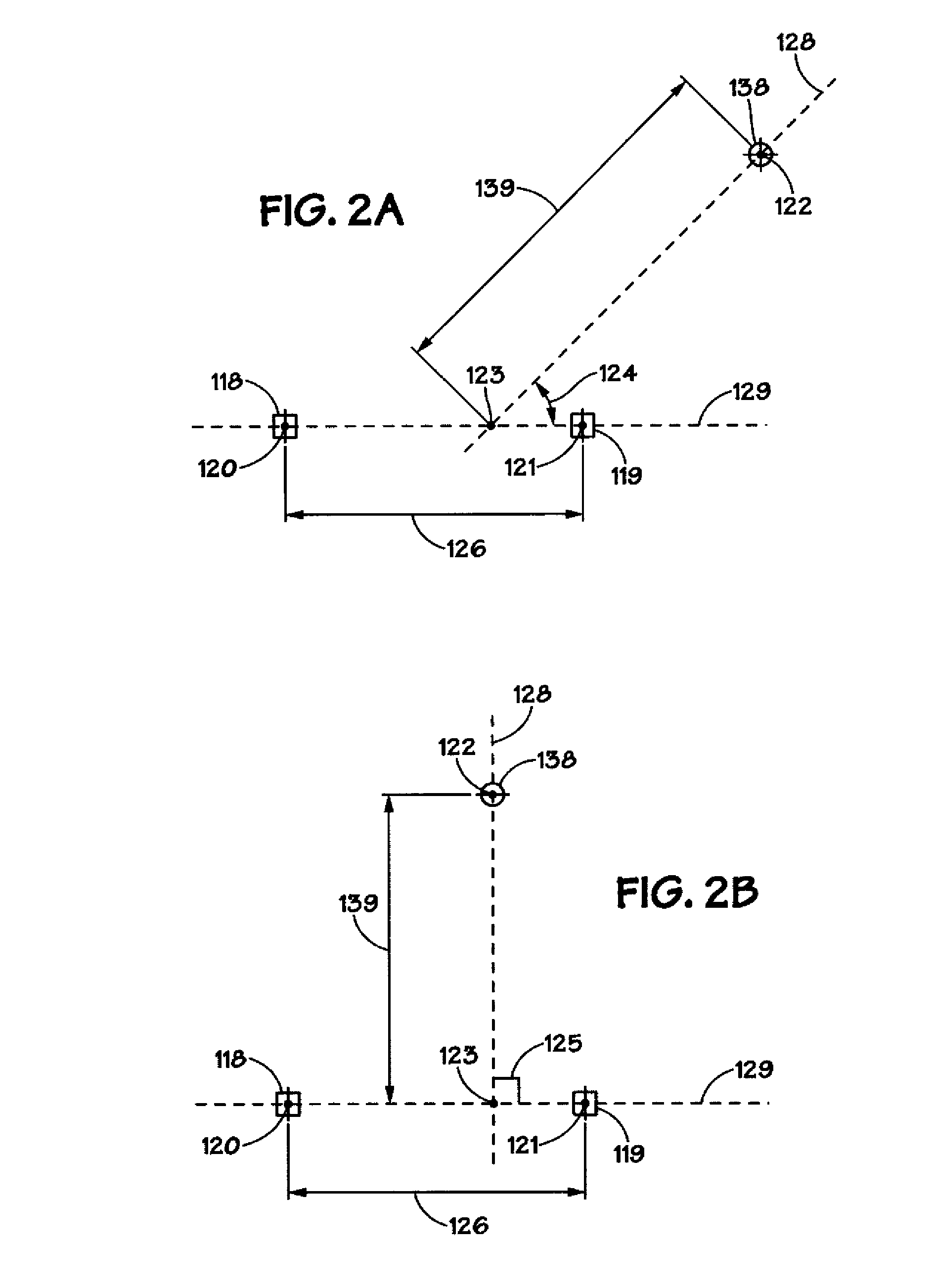
In one illustrative embodiment, the present subject matter is directed to a device adapted to determine the position of a target magnet, wherein the device includes a pair of orthogonal magnetic field sensors laterally disposed along an axis that is substantially transverse to an axis defined by one that is nominally parallel to the direction of the target magnet. In another illustrative embodiment, the subject matter is adapted for use on an automated guided vehicle (AGV), whereby detection of the target magnet's location facilitates correction of the vehicle's heading and position while traversing an AGV system. The present subject matter is also directed to a method whereby the position of a target magnet may be determined by triangulation, utilizing trigonometric calculations based upon the strength and direction of the magnet field to determine the magnet's position relative to the magnetic field sensors.

Description

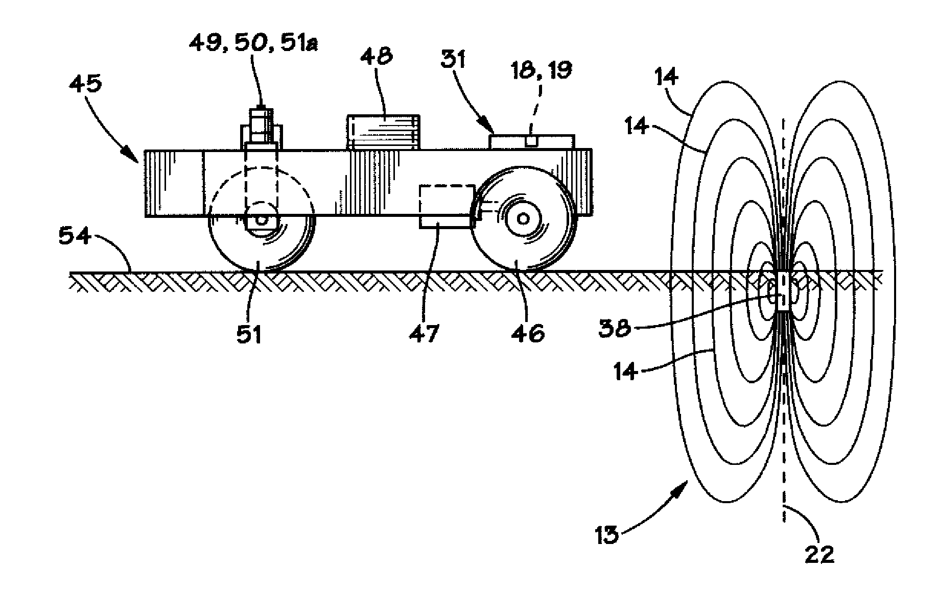
BACKGROUND OF THE INVENTION[0001]1. Field of the Invention[0002]The present invention generally relates to the field of magnetic field sensing and, more particularly, to devices used for magnetic field sensing, detecting the location of magnets, and various methods of using same.[0003]2. Description of the Related Art[0004]Many types of industrial activities, such as manufacturing, packaging, warehousing and shipping, often employ driverless vehicles to perform a variety of movement-related functions. Depending on the industry and application, the types of activities performed by these driverless vehicles are commonly repetitive in nature, and the vehicles would generally be expected to continue these activities within a pre-defined set of operating parameters without significant human interaction or monitoring. Such repetitive and unmonitored activities would include for example: material handling within a factory setting, whereby raw materials or components are moved between locat...

Claims


Application Information

Patent Timeline
IPC IPC(8): G01B7/14
CPCG01R33/02G01D5/145
Inventor DRENTH, JOSEPH B.DRENTH, RONALD R.
Owner JOHN BEAN TECH CORP
Why Eureka
Try Eureka