Combining multiple-port patch antenna

a patch antenna and multi-port technology, applied in the direction of resonant antennas, substantially flat resonant elements, radiating element structural forms, etc., can solve the problems of power combiners occupying a significant amount of circuit-board space, electrical breakdown, and problems such as problems

Active Publication Date: 2009-05-21
RAYTHEON CO
View PDF3 Cites 39 Cited by
  • Summary
  • Abstract
  • Description
  • Claims
  • Application Information

AI Technical Summary

Problems solved by technology

Power combiners, however, occupy a significant amount of circuit-board space.
Problems can also occur with this power-combining approach for high-power applications since all the power is concentrated into one or two microstrip lines, which may be very narrow.
If too much power is fed through the microstrip lines, it may cause an electrical breakdown.
It cannot be used, however, if each port is to be driven by independent microwave sources or if cir...

Method used


Image

  • Combining multiple-port patch antenna
  • Combining multiple-port patch antenna
  • Combining multiple-port patch antenna

Examples


Embodiment Construction

[0030]The following representative descriptions of the present invention generally relate to exemplary embodiments and the inventor's conception of the best mode, and are not intended to limit the applicability or configuration of the invention in any way. Rather, the following description is intended to provide convenient illustrations for implementing various embodiments of the invention. As will become apparent, changes may be made in the function and / or arrangement of any of the elements described in the disclosed exemplary embodiments without departing from the spirit and scope of the invention.

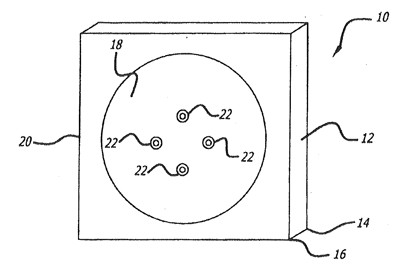
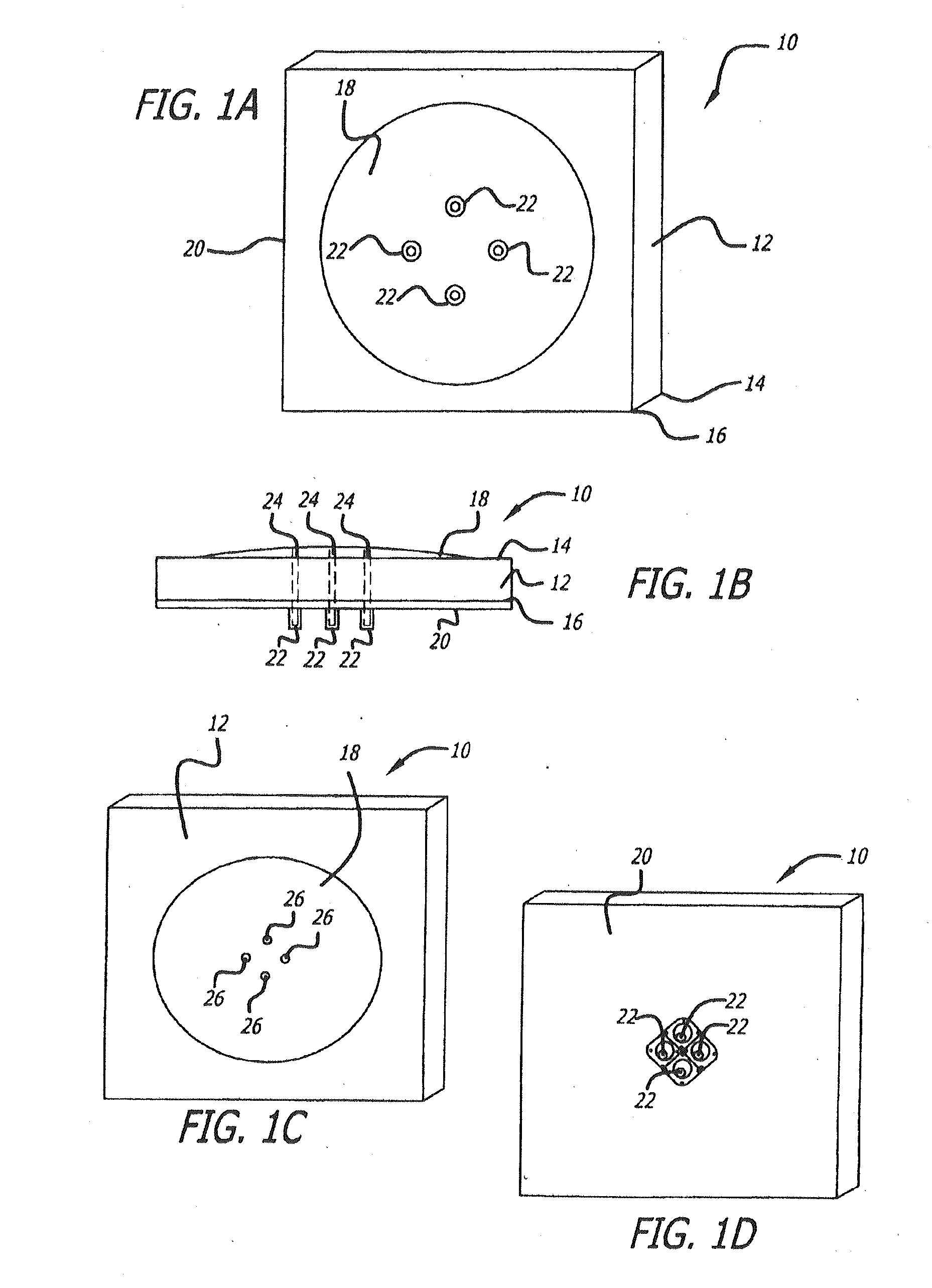
[0031]The present invention eliminates the need to pre-combine the outputs of multiple microwave sources by providing a patch antenna with multiple input ports. The power sources are coupled directly to the antenna, and the power is combined in the antenna itself, rather than using separate circuit-based power combiners. The area that would otherwise be occupied by power combiners can be...


PUM


Abstract

An exemplary apparatus providing an antenna for radiating electromagnetic energy is disclosed as having: a first dielectric substrate having opposite first and second surfaces, a patch of conducting material disposed on the first surface, a ground plane of conducting material disposed of the second surface, at least three input means coupled to a plurality of microstrip feed lines wherein the microstrip feed lines have an aspect ratio suitably configured to maximize antenna bandwidth. Disclosed features and specifications may be variously controlled, adapted or otherwise optionally modified to improve and/or modify the performance characteristics of the antenna. Exemplary embodiments of the present invention generally provide an antenna for providing wideband power combining and wideband radiation functions.

Description

FIELD OF INVENTION[0001]The present invention generally provides improved systems, compositions and methods for an improved antenna for radiating electromagnetic energy; and more particularly, representative and exemplary, embodiments of the present invention generally relate to an improved microstrip patch antenna.BACKGROUND OF INVENTION[0002]Certain applications require the power from multiple microwave sources to be combined in order to create a single high-power output signal, which is then radiated by a single antenna. This is typically accomplished using one or more power combiners, such as microstrip power combiners, that combine the power from multiple amplifiers and feed it to a conventional single- or two-port antenna using one or two microstrip lines. Power combiners, however, occupy a significant amount of circuit-board space. If the outputs of a large number of microwave sources are to be combined, the area occupied by power-combining circuitry can be a significant frac...

Claims


Application Information

Patent Timeline
IPC IPC(8): H01Q9/04H01Q1/38
CPCH01Q3/26H01Q9/045H01Q9/0407
Inventor CROUCH, DAVIDDOLASH, WILLIAM E.
Owner RAYTHEON CO
Why Eureka
Try Eureka