Plug-in antenna

a plug-in antenna and antenna technology, applied in the field of plug-in antennas, can solve the problems of high cost of fabricating and assembling antenna arrays using many of the prior art approaches, not meeting the unique challenges of low-cost plug-in antennas, and not being able to meet the needs of low-cost assembly using pick and place machines, etc., to achieve the effect of low cost, easy assembly and low cos

Active Publication Date: 2012-03-29
RAYTHEON CO
View PDF4 Cites 13 Cited by
  • Summary
  • Abstract
  • Description
  • Claims
  • Application Information

AI Technical Summary

Benefits of technology

[0005]Embodiments of the present invention address these problems by providing a low cost plug-in antenna for plugging directly into a printed circuit board (PCB). Embodiments of the present invention are directed to a low cost antenna that can be interfaced into a transceiver, either for discrete or array applications. Antennas

Problems solved by technology

The prior art for the technology of low cost plug-in antennas, or antennas that connect to a chassis (e.g., a printed circuit board), either a discrete chassis or an array chassis, do not address all of the unique challenges.
One problem is the high cost of fabricating and assembling antenna arrays using many of the prior art approaches, such as soldered connection

Method used


Image

  • Plug-in antenna
  • Plug-in antenna
  • Plug-in antenna

Examples


Embodiment Construction

[0040]Exemplary embodiments of the present invention will now be described in more detail with reference to the accompanying drawings. Like reference numerals refer to like elements throughout.

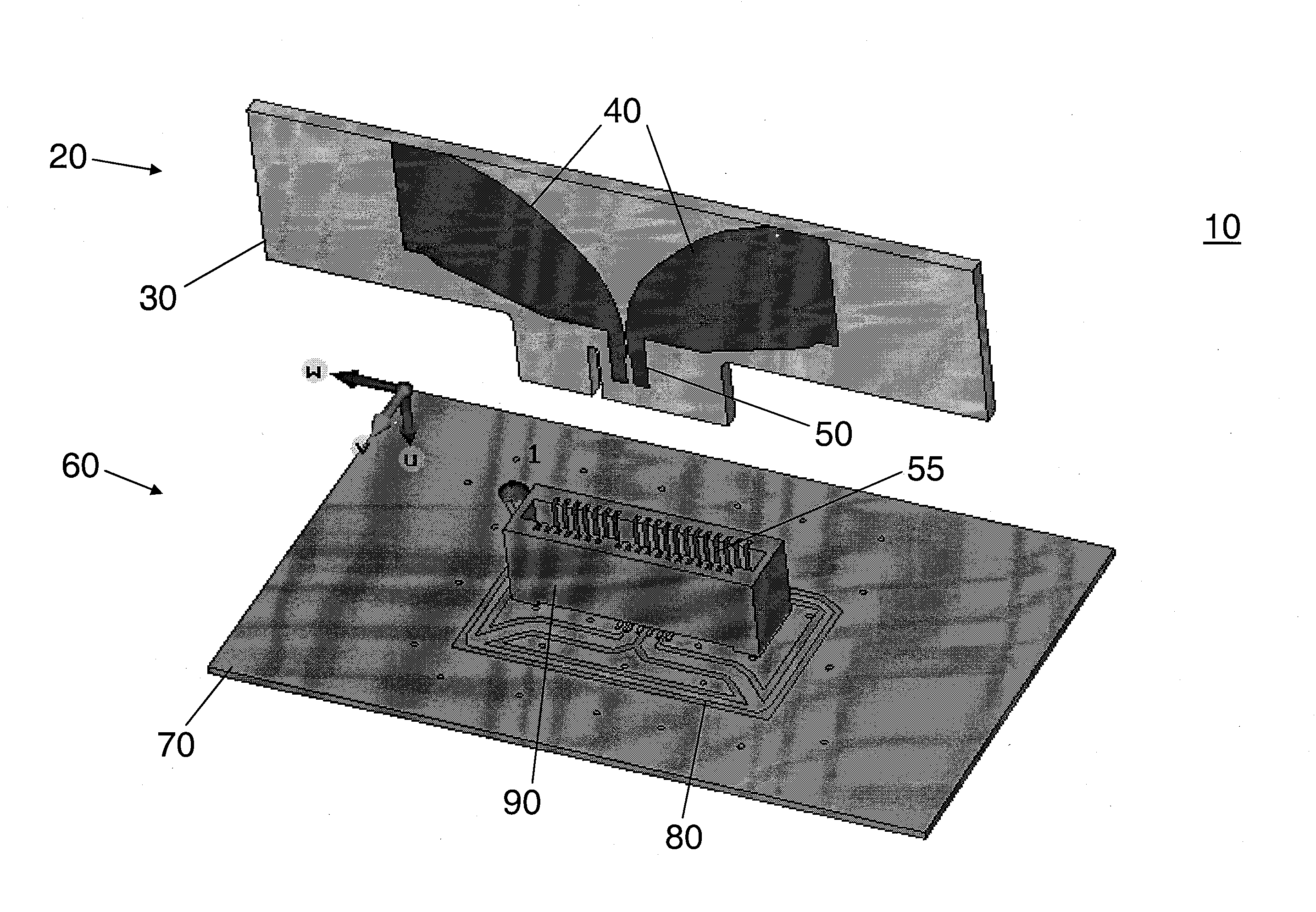
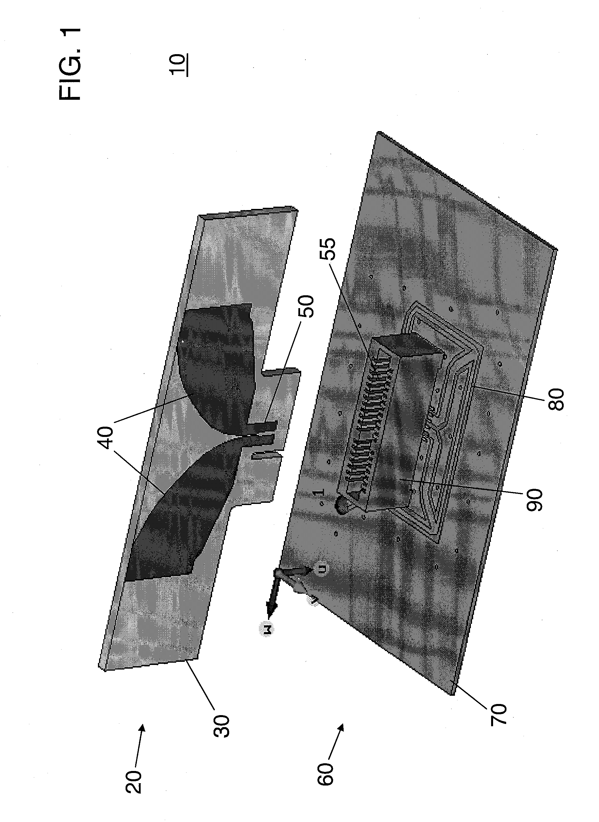
[0041]There are a variety of integration mechanisms for an antenna into an electronic system. Antennas that screw into the transceiver chassis often require manual tools, to insure correct installation. Antenna elements that solder in place can pose difficulties due to the 3-dimensional nature of antennas and processes that are geared to PCB planar soldering. For transceivers, such as wireless handsets, or radars that are capable of being serviced, simple disassembly is required to keep the service costs low and to minimize damage to the device. Other approaches include utilizing pins either soldered to the antenna boards or routed into the boards. However, these are not low cost solutions for assembly of parts onto a standard circuit board because the antenna element cannot be installed by a ...


PUM


Abstract

A modular plug-in antenna array capable of low cost and automated manufacturing is disclosed. The antenna element is designed to work efficiently over a broadband with simplified assembly requirements and to be used in discrete or array applications. Plug-in antennas eliminate the need for external tools, and allow the antenna to be removed, for service, test, and ease of assembly. Many transceivers are assembled using printed circuit board techniques whereon electronic components are mounted using a pick and place process. The plug-in antenna connects directly onto the circuit board; with connectors that are compatible with a pick and place process and which are produced in mass quantities for the computer and telecommunications industry, thus yielding lower costs than traditional high performance RF coaxial connectors. With demands for higher antenna bandwidth, the disclosed simplified plug-in antenna provides an appropriate balance between performance and the ease of modular assembly, manufacture, and costs.

Description

BACKGROUND[0001]1. Technical Field[0002]Aspects of embodiments according to the present invention relate to antennas. More specifically, aspects of embodiments according to the present invention relate to antennas that plug into printed circuit boards (PCBs).[0003]2. Brief Description of the Related Art[0004]The prior art for the technology of low cost plug-in antennas, or antennas that connect to a chassis (e.g., a printed circuit board), either a discrete chassis or an array chassis, do not address all of the unique challenges. One problem is the high cost of fabricating and assembling antenna arrays using many of the prior art approaches, such as soldered connections, which do not lend themselves to low cost assembly using pick and place machines. For example, some designs need expensive connectors, which make them impractical for cost sensitive applications. Other designs do not offer wideband antenna efficiency, or sufficient bandwidth, or proper signal direction to provide the...

Claims


Application Information

Patent Timeline
IPC IPC(8): H01Q1/22
CPCH01Q1/088H01Q21/0087H01Q9/285H01Q1/1207H01Q13/085H01Q21/064H01Q21/06
Inventor LIVINGSTON, STAN W.ADCOOK, SCOTT E.
Owner RAYTHEON CO
Why Eureka
Try Eureka