Power converter

a power converter and converter technology, applied in the direction of ac-dc conversion, ac-dc conversion, efficient power electronics conversion, etc., can solve the cost/efficiency tradeoff in the most applications of power converter design, the power supply for these types of equipment is relatively expensive to construct, and the implementation cost is relatively high, so as to simplify the control circuitry. , the effect of reducing the cost of the control circuitry and facilitating the conversion

Active Publication Date: 2009-05-21
COMMERGY TECH
View PDF27 Cites 17 Cited by
  • Summary
  • Abstract
  • Description
  • Claims
  • Application Information

AI Technical Summary

Benefits of technology

[0004]It is an object therefore of the present invention to provide a power converter that is relatively inexpensive to construct while at the same time being highly efficient in use. It is a further object of the present invention to provide a power converter that is relatively simple to construct and manufacture.STATEMENTS OF INVENTION
[0045]In a further embodiment of the invention there is provided a power converter in which the means to sense the intermediate voltage fed to the output is provided by way of a differential sensing function between the input rail and the output voltage of the pre-regulator stage. In one embodiment, the differential sensing function comprises a PNP transistor. This is a simple configuration of means to sense the intermediate voltage fed to the output.

Problems solved by technology

Usually, there is a cost / efficiency tradeoff in most applications of power converter design.
Heretofore, this has often resulted in the power supply for these types of equipment being relatively expensive to construct.
There are however problems with such an approach as it tends to be relatively expensive to implement while still not being highly efficient i.e. in the range of 90%+ efficiency.

Method used


Image

  • Power converter
  • Power converter
  • Power converter

Examples


Embodiment Construction

[0047]The invention will now be more clearly understood from the following description of some embodiments thereof given by way of example only with reference to the accompanying drawings in which:

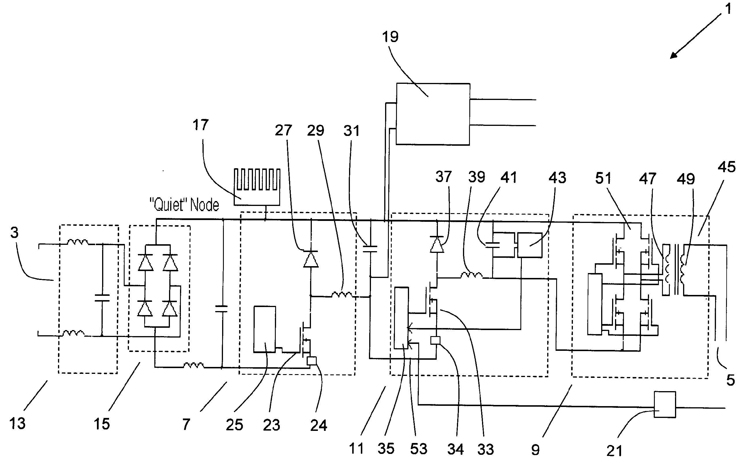
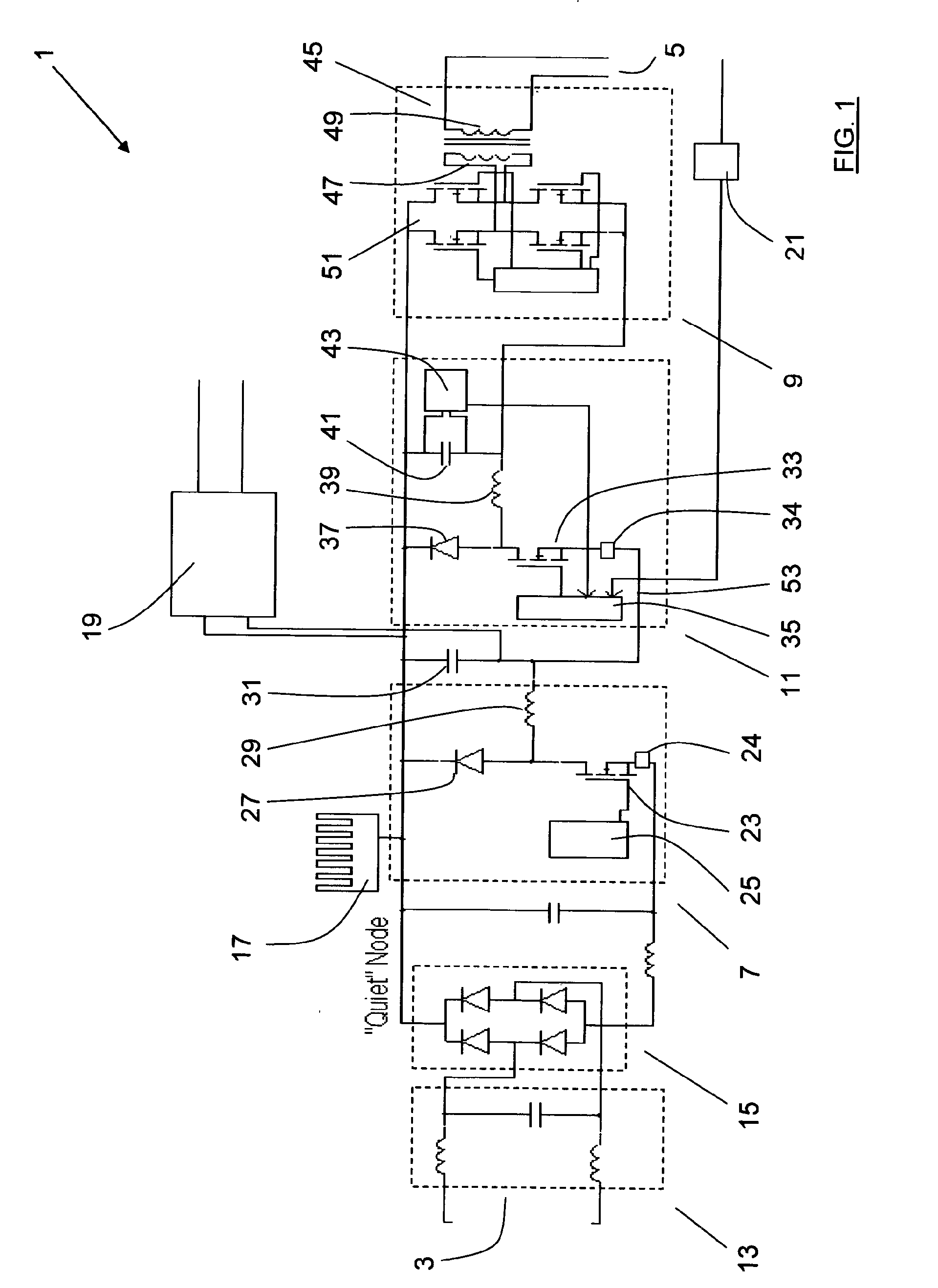
[0048]FIG. 1 is a diagrammatic, part schematic representation of a power converter according to the invention;

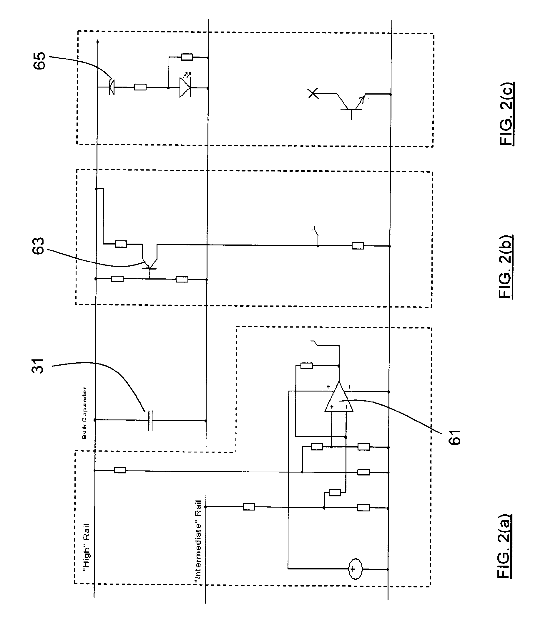
[0049]FIGS. 2(a), 2(b) and 2(c) are schematic representations of various differential sensing means used in the power converter according to the invention;

[0050]FIG. 3 is a diagrammatic, part schematic representation of an alternative construction of power converter for enhanced electromagnetic compatibility performance;

[0051]FIG. 4 is a diagrammatic representation of an arrangement of transformer windings for use with the power converter according to the present invention;

[0052]FIG. 5 is a diagrammatic representation of a power converter having a buck pre-regulation stage that is known in the art; and

[0053]FIG. 6 is a schematic representation of a power converter having a buck pre...


PUM


Abstract

This invention relates to a power converter (1) comprising a converter input (3), a converter output (5), a power factor correction (PFC) stage (7) and an isolation stage (9). The PFC stage (7) is implemented by way of a buck PFC with low side drive and low side current sensing, There is provided a third stage, an intermediate buck pre-regulation stage (11), intermediate the buck PFC stage (7) and the isolation stage (9), Control of the power converter output voltage is achieved by varying the duty cycle of the intermediate buck pre-regulation stage (11) and therefore the isolation stage (9) may be an unregulated stage operated as a fixed DCDC voltage converter. The isolation stage (9) is operated as a 50%-50% duly cycle double ended stage. The configuration of power converter allows for a relatively inexpensive, highly efficient converter with 90%+ efficiency and simplified control.

Description

[0001]This invention relates to a power converter. More particularly, this invention relates to an AC / DC converter.[0002]Power converters and in particular AC / DC power converters are used in a wide range of applications. Generally speaking, these power converters are used to transform the incoming AC mains supply line voltage to one or more DC voltages suitable for use with the equipment that the power converter is charged with supplying voltage to. In many cases, the power converter will transform the AC mains line voltage into several DC line voltages such as in the case of electronic equipment. When designing a power converter, there are essentially two main considerations taken into account, namely cost and efficiency. Usually, there is a cost / efficiency tradeoff in most applications of power converter design.[0003]Certain applications, such as personal computer power supplies, server power supplies and telecommunications equipment power supplies, typically require highly effici...

Claims


Application Information

Patent Timeline
Patent Type & Authority Applications(United States)
IPC IPC(8): H02M1/42
CPCY02B70/12H02M1/42Y02B70/10
Inventor YOUNG, GEORGETOMLINS, GARRYBARRY, MICHAEL JOHNBARNARD, JACOBUS MARTHINUS
Owner COMMERGY TECH
Why Eureka
Try Eureka