Melting and mixing of materials in a crucible by electric induction heel process

Active Publication Date: 2009-05-21
INDUCTOTHERM INDS
View PDF8 Cites 24 Cited by
  • Summary
  • Abstract
  • Description
  • Claims
  • Application Information

AI Technical Summary

Benefits of technology

[0005]In one aspect the present invention is apparatus for, and method of, electric induction heating and melting of a transition material that is non-electrically conductive in the solid state and is electrically conductive in the non-solid state in a heel electric induction heating and melting process. Multiple coils are provided around the height of the crucible, which contains a heel of molten transition material at the start of the melting process. Initially, relatively high magnitude, in-phase melting power at a relatively high frequency is sequentially supplied to each coil from one or more power supplies until the crucible is filled with transition material. When the crucible is substantially filled with transition material, the output frequency of the one or more power supplies is lowered to a stirring frequency along with the magnitude of the output power, while an out-of-phase relationship is established between the output voltages of the power supplies to achieve a preferred electromagnetic stir pattern.

Problems solved by technology

Inductively heating and melting by the heel process when the material is non-electrically conductive in the solid state and electrically conductive in the molten state (referred to as a transition material), such as silicon, is problematic in that addition of solid non-electrically conductive charge to the molten heel must be adequately melted and mixed so that the added solid charge does not accumulate to form aggregate non-electrically conductive solid masses in, or over, the surface of the molten material.

Method used


Image

  • Melting and mixing of materials in a crucible by electric induction heel process
  • Melting and mixing of materials in a crucible by electric induction heel process
  • Melting and mixing of materials in a crucible by electric induction heel process

Examples


Embodiment Construction

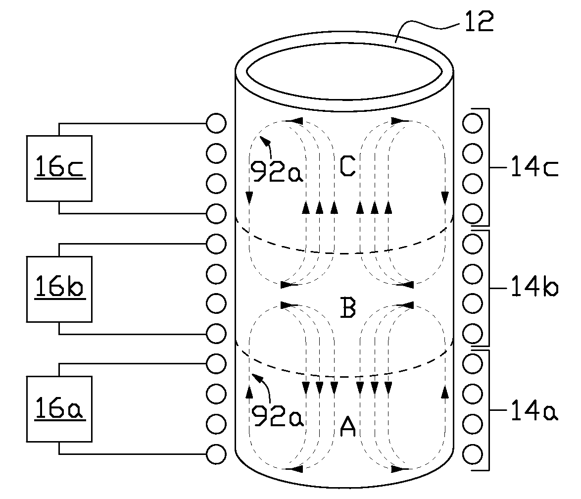
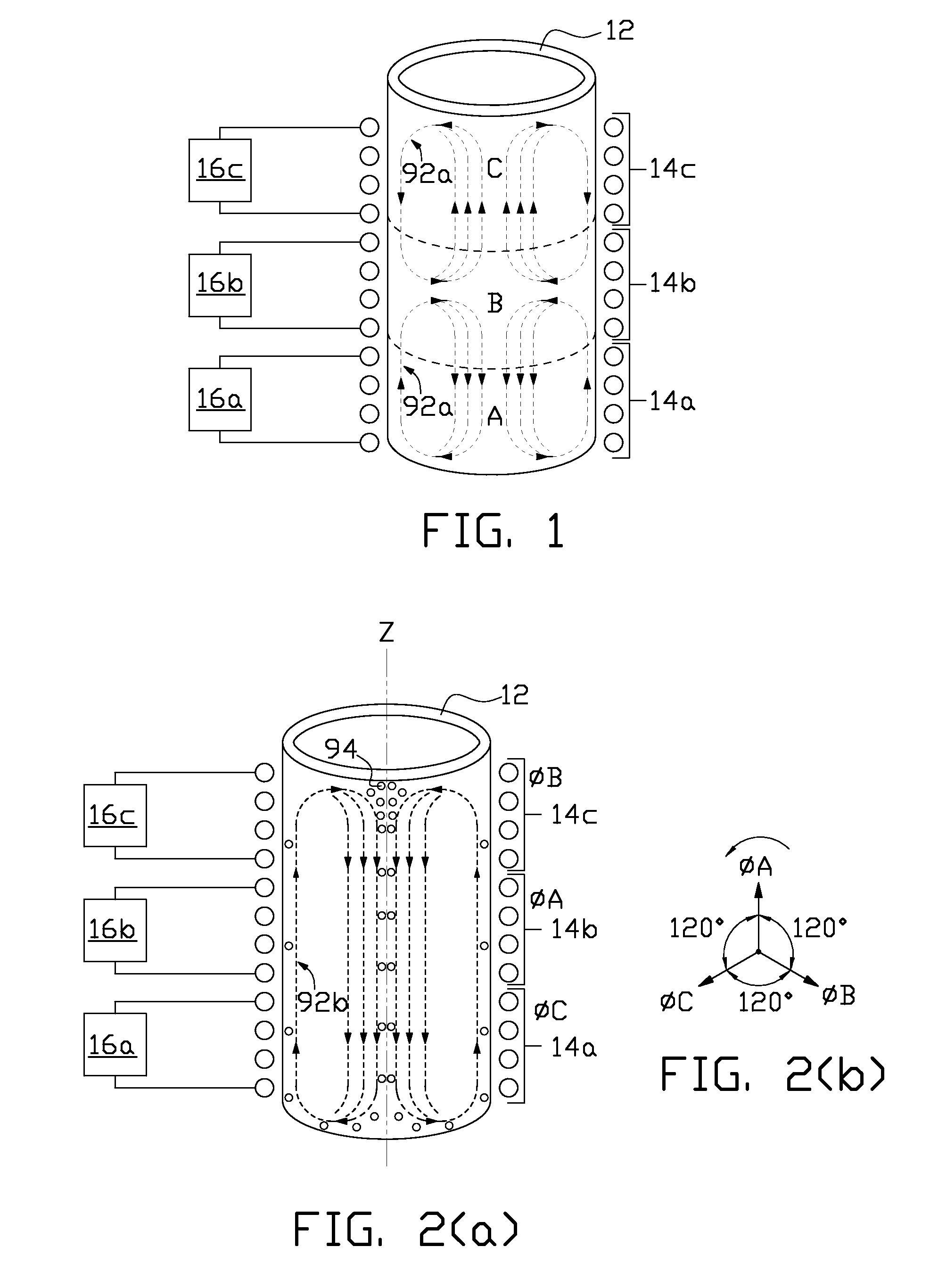
[0012]Referring to FIG. 1 and FIG. 2(a), in one non-limiting example of the present invention, refractory crucible 12 is exteriorly surrounded by lower volume induction coil 14a, central volume induction coil 14b and upper volume induction coil 14c. Interior lower volume A of the crucible is generally the interior region of the crucible surrounded by lower volume induction coil 14a; interior central volume B of the crucible is generally the interior region of the crucible surrounded by central volume induction coil 14b; and interior upper volume C of the crucible is generally the interior region of the crucible surrounded by upper volume induction coil 14c. The approximate boundaries of each interior volume are indicated by dashed lines in the figures. Lower volume induction coil 14a is disposed around at least the minimum level of operating heel of material to be generally maintained in the furnace. Separate power supplies 16a, 16b and 16c supply ac power to each of the lower, cent...


PUM

PropertyMeasurementUnit
melting temperatureaaaaaaaaaa
frequencyaaaaaaaaaa
frequency f2aaaaaaaaaa

Abstract

Apparatus and method are provided for electric induction heating and melting of a transition material that is non-electrically conductive in the solid state and electrically conductive in the non-solid state in an electric induction heating and melting process wherein solid or semi-solid charge is periodically added to a heel of molten transition material initially placed in a refractory crucible. Induction power is sequentially supplied to a plurality of coils surrounding the exterior height of the crucible at high power level and high frequency with in-phase voltage until a crucible batch of transition material is in the crucible when the induction power is reduced in power level and frequency with voltage phase shifting to the induction coils along the height of the crucible to induce a unidirectional electromagnetic stir of the crucible batch of material.

Description

CROSS REFERENCE TO RELATED APPLICATIONS[0001]This application claims the benefit of U.S. Provisional Application No. 60 / 988,783, filed Nov. 17, 2007, hereby incorporated by reference in its entirety.FIELD OF THE INVENTION[0002]The present invention relates to electric induction melting and mixing of materials that are in a non-electrically conductive state when gradually added to an induction refractory crucible initially holding a heel, or bottom layer, of electrically conductive molten material.BACKGROUND OF THE INVENTION[0003]Batch and heel are two types of electric induction processes for heating and melting of electrically conductive materials. In the batch process, a crucible is filled with a batch of electrically conductive solid charge that is melted by electric induction and then emptied from the crucible. In the heel process, a molten heel (bottom pool) of electrically conductive material is always maintained in the crucible while solid electrically conductive charge is ad...

Claims


Application Information

Patent Timeline
Patent Type & Authority Applications(United States)
IPC IPC(8): F27D23/04F27D11/06F27B14/06F27B14/10F27D27/00
CPCF27B14/061F27B14/14F27D99/0006H05B6/32H05B6/44H05B6/067H05B6/34H05B6/367H05B6/24H05B2213/02
Inventor FISHMAN, OLEG S.
Owner INDUCTOTHERM INDS
Why Eureka
Try Eureka